Loosen vacuum breaker to valve.
Mount xture
Pull ush connection forward through wall.
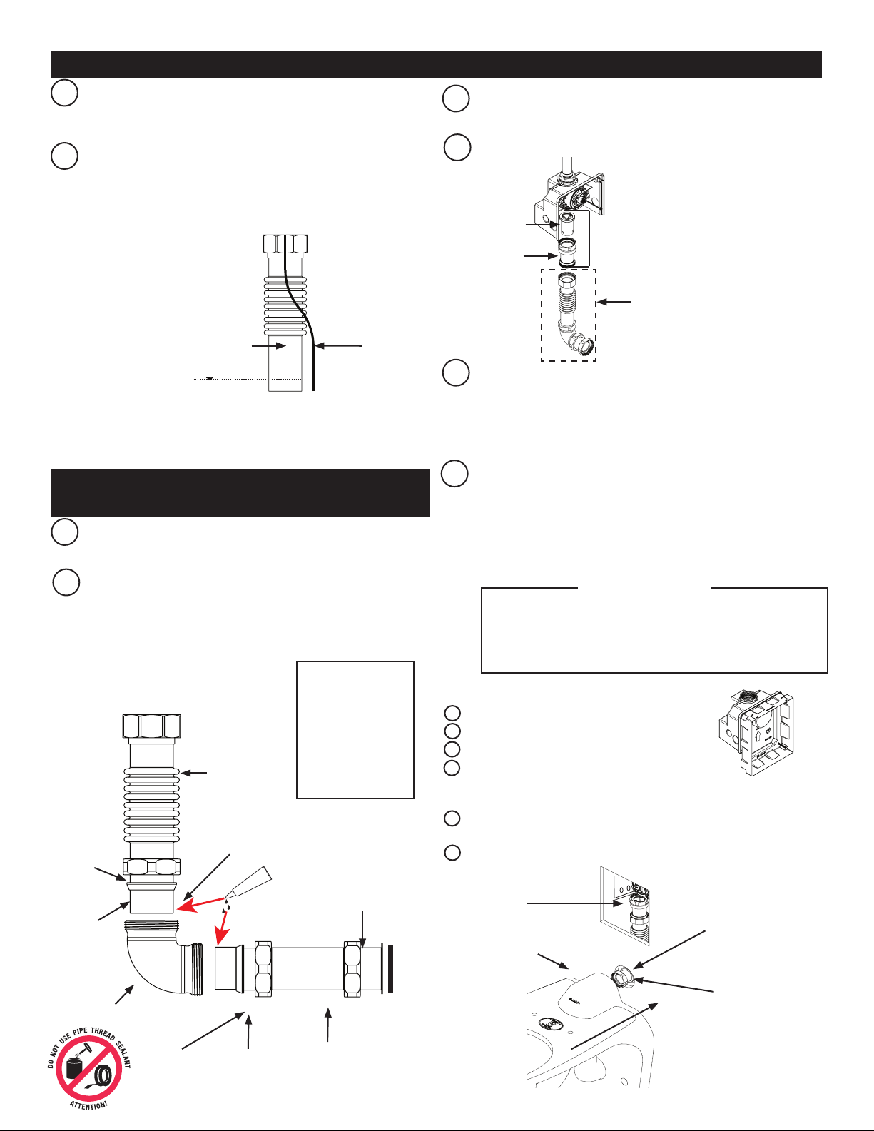
Pre-install escutcheon and ttings in the following order:
1. Wall trim plate
2. Coupling
3. Friction ring
4. Gasket
5. Escucheon
Connect coupling (2) to spud, wrench tight.
Slide wall trim plate against wall.
Re-connect vacuum breaker to valve.
7
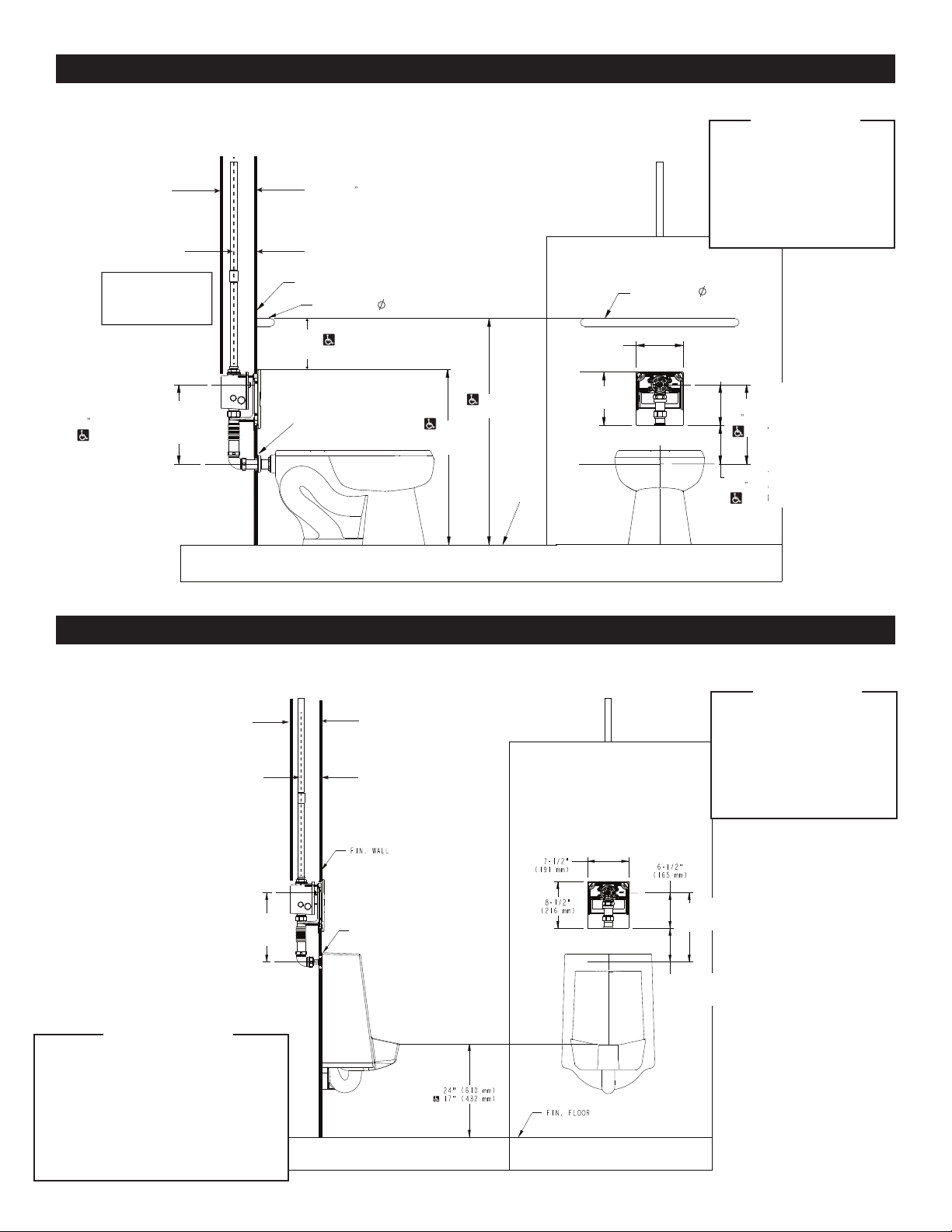
FOR REAR SPUD URINALS
F, L
F
G
H
I
J
K
L
FOR FLOOR MOUNT REAR SPUD FIXTURES (WATER CLOSET)
Adjustable Tube
Coupling
nut
Poly washer
Elbow
Taper towards
elbow
Coupling nut
A
B
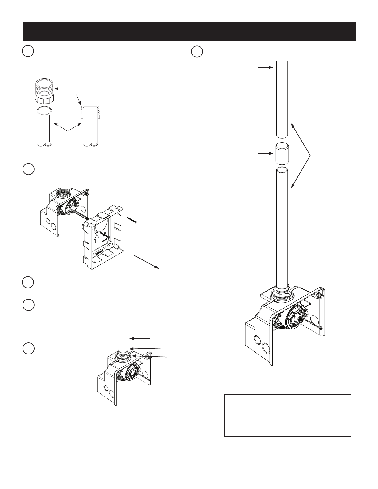
Cut F-1 ush connection to length as needed for particular rough-in.
• Consult rough-in
Connect F-1 ush connection and adjustable tube to the elbow
using coupling and poly washer. Apply Loctite to tube ends,
insert tube ends into elbow, and tighten coupling securely (Do not
apply Loctite to coupling threads).
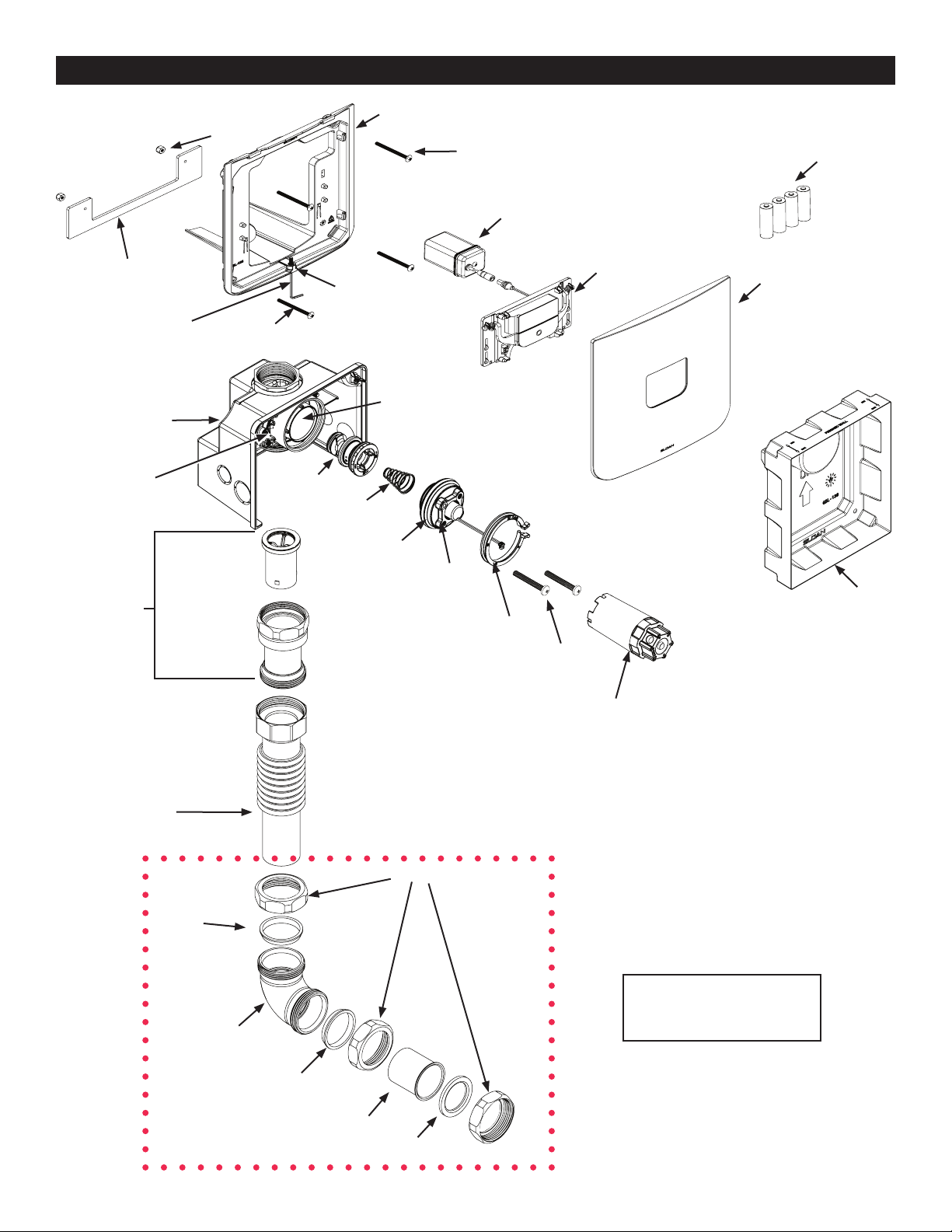
F-1 Flush Connection
Poly Washer
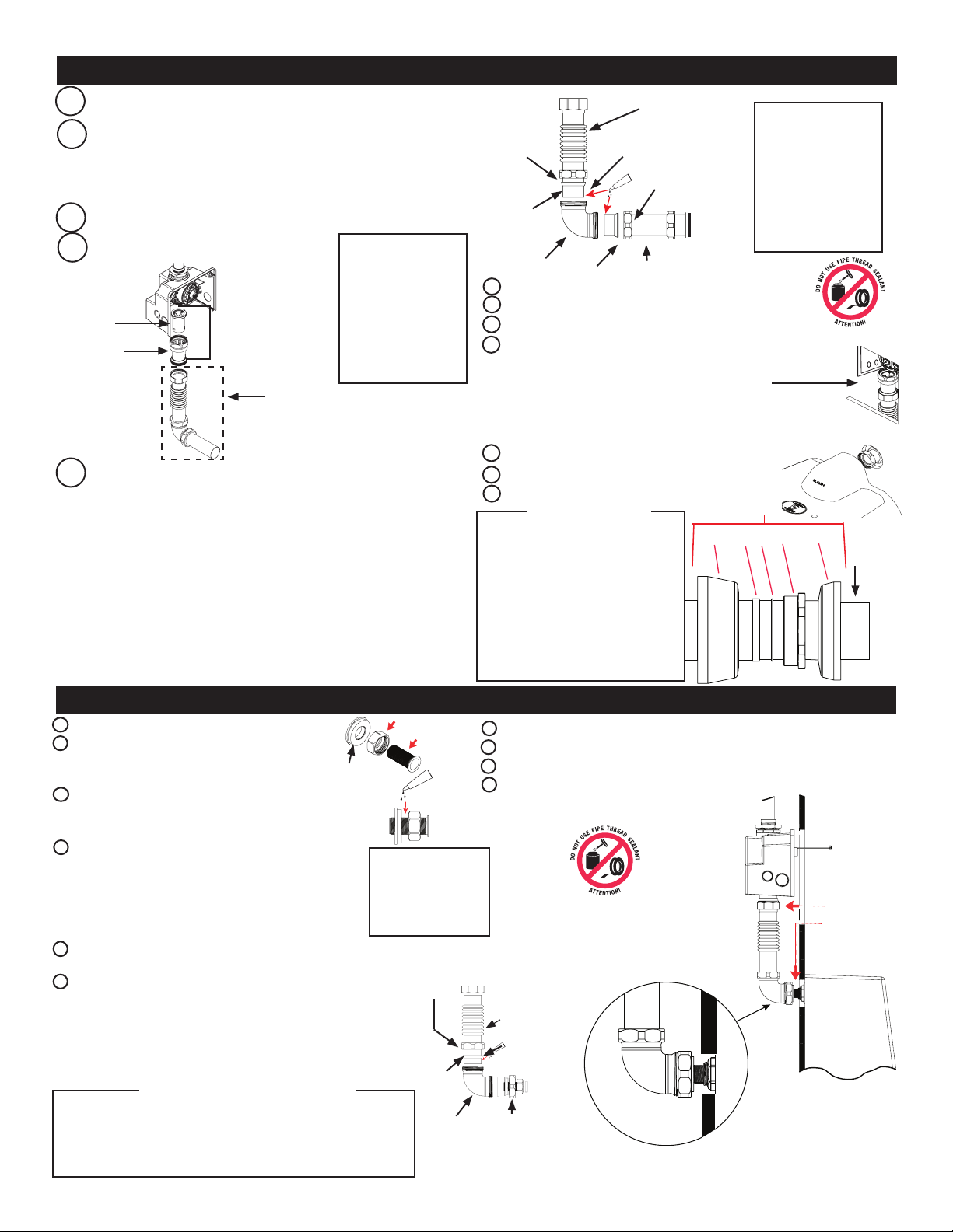
CInsert V-651 vacuum breaker kit into vacuum breaker casing.
Attach to valve hand tight.
Attach ush connection to vacuum breaker.
D
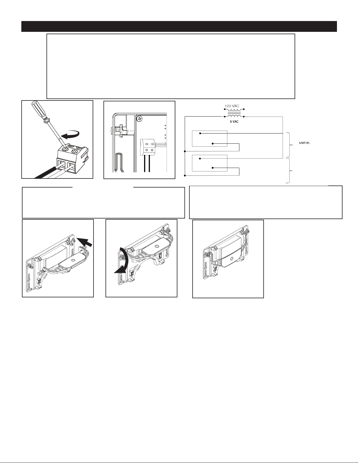
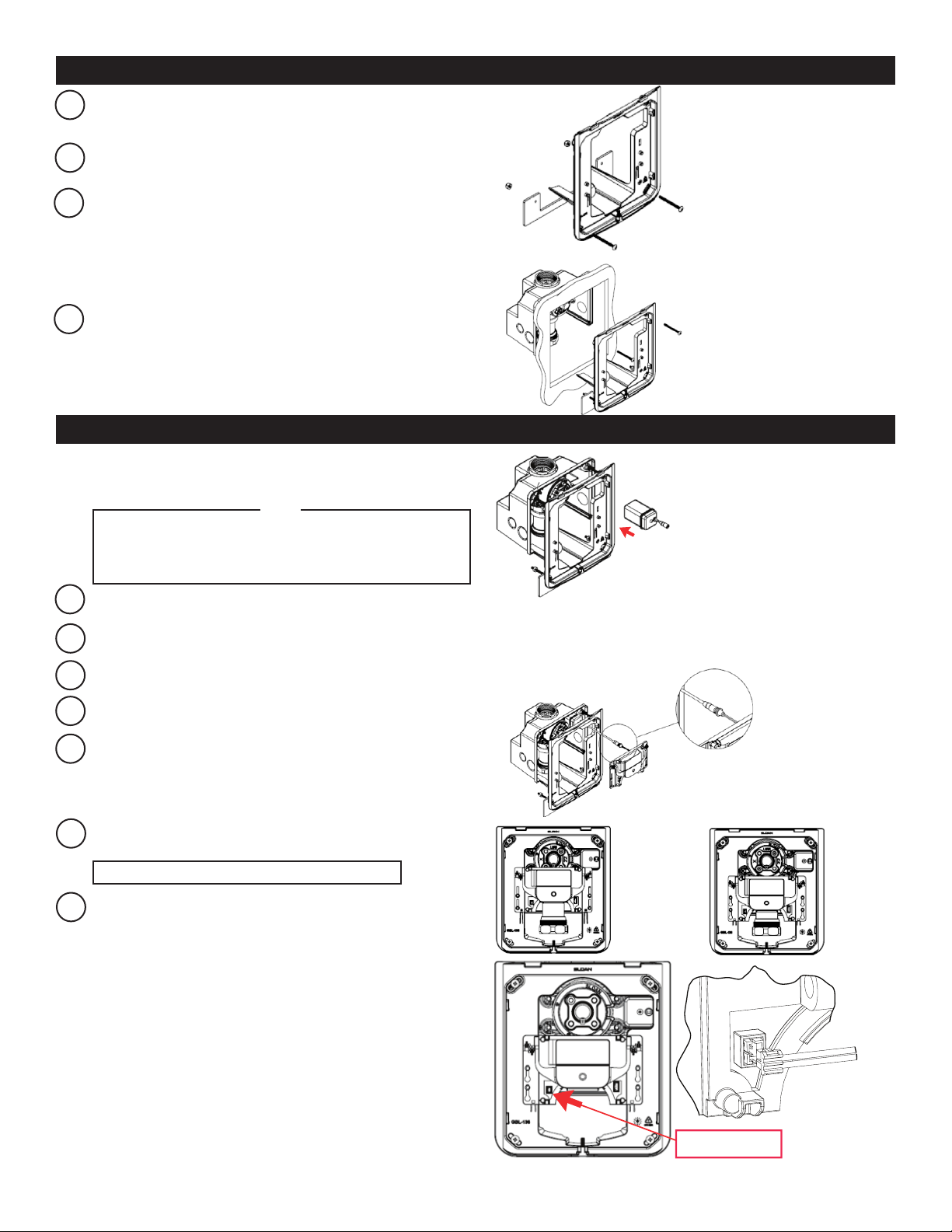
EFor hardwire use only: insert conduit and tightly secure it to the wall
box. Run transformer wires through the conduit to the wall box.
NOTE: TRANSFORMER NOT PROVIDED. IT IS VERY
IMPORTANT THAT THE OUTPUT VOLTAGE OF THE
TRANSFORMER BE 6VAC FOR THE UNIT TO FUNCTION
PROPERLY. SLOAN EL-386 OR EL-451 IS RECOMMENDED.
Finish wall. Use supplied mud guard to protect valve during nishing
process.
• Use two (2) mounting screws, if needed, to hold mud
guard to wall box
• Use the marks on mud guard to make sure nished wall
is between 3 ¼” and 4 ¼” from the center line of the pipe.
Vacuum Breaker
V-651-A Kit
Vacuum Breaker
casing
Flush Connection
Wall
opening
If needed, trim urinal ush tube.
Slide 3/4" coupling over urinal ush tube.
If cutting tube, thread adapter rst, then cut. After
cut, remove adapter to help chase/clean threads.
Thread F-28 brass ange onto urinal ush tube.
Amount of thread engagement will depend on rough-in.
Use provided Loctite to secure and seal F28 ange.
Apply Loctite to tube threads (completely around tube)
where ange will sit on tube. Then thread ange into Loctite.
Ensure Loctite is visible on both sides of ange. Allow time
for Loctite to "set", approx. 30 minutes.Slide F2 coupling over
urinal connection tube, and then install urinal connection tube
to urinal spud and tighten spud coupling.
Secure urinal ush tube to elbow using
1-1/2” gasket.
B
C
Adjustable
Tube
Taper toward
elbow
Coupling nut
Coupling
nut
Poly
washer
Elbow
G. Finish wall. Use supplied mud guard to protect valve during nish-
ing process.
• Use two (2) mounting screws, if needed, to hold mud gaurd to
wall box.
• Use the marks on mud guard to make sure finished wall is
between 3 1/4" and 4 1/4" from the center line of the pipe.
Hang urinal on mounting bracket.
Loosen vacuum breaker to valve.
Make spud connection behind the wall.
Re-connect vacuum breaker to valve.
I, K
J
Loctite must cure for
24 hours before turning
on water; otherwise the
Loctite will wash out
and joint will leak.
V500A RB
Loctite must cure
for 24 hours before
turning on water
otherwise the
Loctite will wash
out and joint will
leak
F28 Flange
Loctite must cure
for 24 hours before
turning on water
otherwise the
Loctite will wash
out and joint will
leak
A
B
C
F
D
G
H
I
J
K
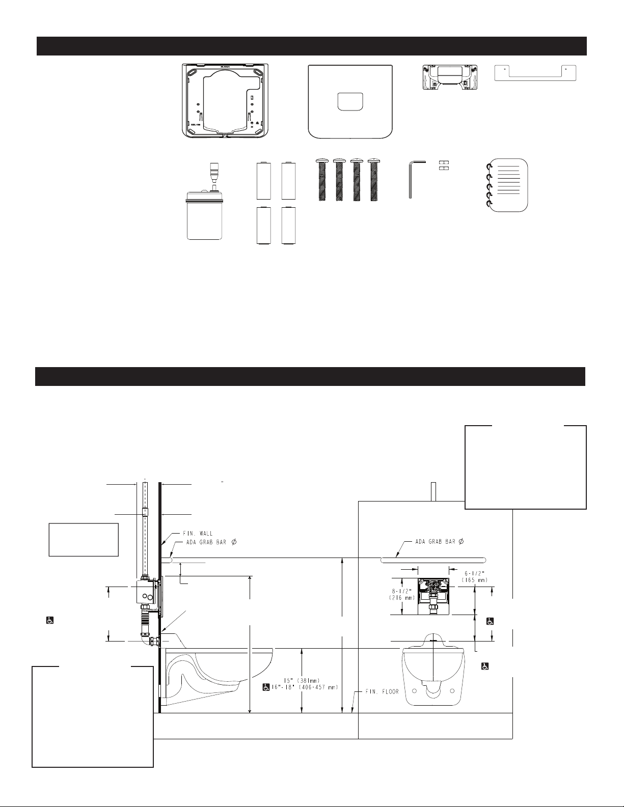
Wall plate opening must be a
minimum 7-3/8” wide x 8-3/8”
tall (187 mm wide x 213 mm
tall) to maximum 7-5/8” wide
x 8-5/8” tall (194 mm wide x
219 mm tall). Valve must be
centered horizontally within
opening.
!!! IMPORTANT !!!
Wall plate opening must be a minimum 7-3/8” wide x
8-3/8” tall (187 mm wide x 213 mm tall) to maximum
7-5/8” wide x 8-5/8” tall (194 mm wide x 219 mm tall).
Valve must be centered horizontally within opening.
!!! IMPORTANT !!!