OneFex CS-IO204 Manuel utilisateur

1
/ 13
CS-IO204 User Manual
CS-IO204
Serial I/O Module
Manual

2
/ 13
CS-IO204 User Manual
CS-IO204.......................................................................................................................................................1
1PRODUCT INTRODUCTION ..............................................................................................................5
1.1 FEATURES ............................................................................................................................................5
1.2 PARAMETER .........................................................................................................................................5
1.3 ITEM SELECTION...................................................................................................................................6
1.4 DIMENSION........................................................................................................................................... 6
2WIRING INSTRUCTIONS....................................................................................................................6
2.1 TERMINAL DEFINITION.......................................................................................................................... 6
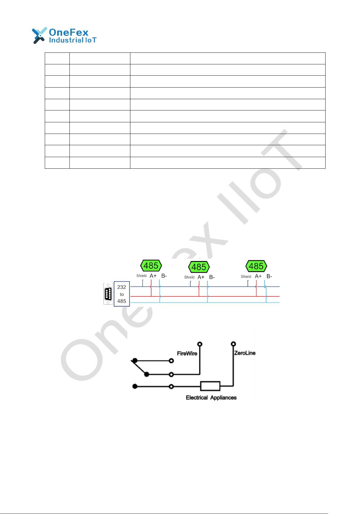
2.2 COMMUNICATION WIRING.................................................................................................................... 7
2.2.1 RS485 Wiring......................................................................................................................7
2.3 DO WIRING ..........................................................................................................................................7
2.3.1 Low Load Wiring.................................................................................................................8
2.3.2 AC 220V Load Device Wiring.............................................................................................8
2.3.3 AC 380V Load Device Wiring 【With Zero Line】.............................................................9
2.3.4 AC 380V Load Device Wiring【Without Zero Line】.........................................................9
2.4 DIGITAL INPUT WIRING.......................................................................................................................10
3PARAMETERS AND WORKING MODE CONFIGURATION ........................................................10
3.1 DEVICE AND PC CONNECTION SETTINGS .........................................................................................10
3.2 DEVICE ADDRESS...............................................................................................................................10
3.2.1 Introduction.......................................................................................................................10
3.2.2 Device Communication Address Reading........................................................................11
3.2.3 Offset Address Setting and Reading ................................................................................11
3.2.4 Baud Rate Reading and Setting.......................................................................................12
3.3 WORKING MODE ................................................................................................................................12
3.3.1 Normal Mode ....................................................................................................................12
3.3.2 NOLock Linkage Mode Mode...........................................................................................12
3.3.3 Lock Linkage Mode...........................................................................................................13
3.3.4 All Channel Lock Linkage.................................................................................................13
3.3.5 2Device NOLock Linkage.................................................................................................13
3.3.6 2Device Lock Linkage.......................................................................................................14
3.3.7 Working Mode Configuration............................................................................................14
4DEVELOPMENT DATA INSTRUCTION..........................................................................................15
4.1 COMMUNICATION PROTOCOL INSTRUCTION......................................................................................15
4.2 MODBUS REGISTER INSTRUCTION..................................................................................................... 15
4.3 COMMAND LIST ..................................................................................................................................17
4.4 COMMAND DETAILS............................................................................................................................17
4.4.1 Control DO........................................................................................................................17
4.4.2 Query DO Status ..............................................................................................................18
4.4.3 Optocoupler Input .............................................................................................................18
4.4.4 Flash ON Flash OFF Command.......................................................................................19
4.4.5 All ON and All OFF Command .........................................................................................20
4.4.6 Active Reporting Protocol.................................................................................................21
5PRODUCT MAINTENANCE..............................................................................................................21
5.1 DEVICE USAGE ENVIRONMENT..........................................................................................................21
5.2 FAQ.................................................................................................................................................... 21
5.2.1 RS485 /RS232 communication, no response when device control .................................21
5.2.2 The DO can only be turned on but not turned off.............................................................22
5.2.3 485 interface cannot be used to establish communication and control After the I/O
module powered on......................................................................................................................22

3
/ 13
CS-IO204 User Manual
5.2.4 Multiple devices on the 485 bus and ON/OFF operation failed to send the broadcast
address 254..................................................................................................................................23
5.2.5 PLC and the device cannot communicate normally .........................................................23
6AFTER-SALE SERVICE....................................................................................................................24
6.1 COMMITMENT .....................................................................................................................................24
6.2 DISCLAIMER........................................................................................................................................ 24
7UPDATE HISTORY............................................................................................................................24

4
/ 13
CS-IO204 User Manual
Notice
❖Please read this manual carefully before use and save it for reference.
❖Please follow to the operating procedures and precautions in this manual.
❖Please open the package carefully and check whether the device and
accessories have been damaged due to transportation when you receive the device.
Please contact us for return processing once damage occurs.
❖Please do not repair it yourself, and contact our technical support department
directly if the device fails.

5
/ 13
CS-IO204 User Manual
1 Product Introduction
CS-IO series products are serial IO module using standard Modbus-RTU protocol,
supporting RS485/232. Support wide voltage power supply, multi-channel input and
output control, which can be widely used in various application scenarios such as
industrial production, agriculture, smart city and office buildings.
1.1 Features
◆DC 9-28V wide voltage power supply, support anti-reverse connection;
◆2-way DO contact isolation, normally ON and normally OFF, 10A 250VAC / 10A
30VDC;
◆4-way DI, with optocoupler isolation, used for switch detection, supports dry and
wet contacts;
◆LED indication; 1 for power and working status, 4 for DO status;
◆SupportsIsolatedRS485Communicationinterface,power isolationplussignal isolation,
reliable communication;
◆Communication baud rate: 300bps~38400bps (, It is 9600 by default and
can be modified by software);
◆Support standard Modbus RTU protocol, read and write by registeraddress;
◆0-255; Built-in address DIP switch; Set by software
◆Support input and output linkage, such as local linkage or dual-computer
linkage, which is convenient for multi-terminal control;
◆Support debugging software for setting parameters and IO control;
◆Support software and hardware customization. Contact Us for details.
1.2 Parameter
Paremater
Contact capacity
10A/30VDC
10A/250VAC
Durability
100,000 times (Electrical)
10,000,000 times (Mechanical)
Data interface
RS485
Rated voltage
DC 9-28V
Power indication
1 red LED
(power, always on; working: flashing)
Output indication
2 red LEDs (DO on and off)
Working temperature
-40℃~85℃, Industrial Grade
Size
95*50*32mm
Weight
77g
Default communication format
9600,n,8,1
Baud rate
300~38400bps

6
/ 13
CS-IO204 User Manual
Functions
Flash ON Flash OFF
All ON All OFF
NOLock Linkage Mode
Local Self-locking Linkage
Interlock
Dual-machine Non-locking Linkage
Dual-machine Self-locking Linkage
Software support
Working mode change
DO independent control
DI status query
Overall DO control;
Debugging information query;
Support various configuration software;
support Labview, etc.
Installation
Mounting Ears
1.3 Item Selection
Item #
DO
DI
Analog
RS485
Address Dial
CS-IO101
1
1
0
RS485 * 1
Address Dial
CS-IO204
2
4
0
RS485 * 1
Address Dial
CS-IO222A
2
2
2(0-20mA)
RS485 * 1
Address Dial
CS-IO404A
4
0
4(0-20mA)
RS485 * 1
Address Dial
CS-IO404
4
4
0
RS485 * 1
Address Dial
CS-IO606
6
6
0
RS485 * 1
Address Dial
CS-IO808
8
8
0
RS485 + RS232
CS-IO1600DI
0
16
0
RS485 + RS232
Address Dial
CS-IO1600
16
0
0
RS485 + RS232
Address Dial
CS-IO3200
32
0
0
RS485 + RS232
Address Dial
1.4 Dimension
95*50*32mm
2 Wiring Instructions
2.1 Terminal Definition
No.
Pin
Instruction
1
+
Positive Power Supply
2
-
Negative Power Supply
3
A+
RS485 communication A+
4
B-
RS485 communication B-

7
/ 13
CS-IO204 User Manual
5
IN1
1st DI
6
IN2
2nd DI
7
IN3
3rd DI
8
IN4
4th DI
9
Normally ON
The 2nd DO normally ON terminal
10
Public
The 2nd DO public terminal
11
Normally OFF
The 2nd DO normally ON terminal
12
Normally ON
The 1st DO normally ON terminal
13
Public
The 1st DO public terminal
14
Normally OFF
The 1st DO normally ON terminal
2.2 Communication Wiring
By default, its address is 1, The host computer software can use the
default address 1 to communicate with the device (or broadcast address 254,
which is only applicable when one device is mounted on the network).
2.2.1 RS485 Wiring
2.3 DO Wiring
The DO is single-pole, double-throw, and each circuit has three terminals, one
group is normally ON and the other is normally OFF (normally ON contacts are
generally used), and the terminal identification is subject to the indications on the
film.

8
/ 13
CS-IO204 User Manual
2.3.1 Low Load Wiring
Applicable for non-resistive load current< 3A or resistive load current < 5A
2.3.2 AC 220V Load Device Wiring

9
/ 13
CS-IO204 User Manual
2.3.3 AC 380V Load Device Wiring 【With Zero Line】
2.3.4 AC 380V Load Device Wiring【Without Zero Line】

10
/ 13
CS-IO204 User Manual
Please add an AC contactor/intermediate relay between this device and the load in
the following four cases:
1. Load rated voltage>30VDC
2. Load rated voltage>250VAC
3. Non-Resistive Load Current>3A
4. Resistive load current>5A
2.4 Digital Input Wiring
3 Parameters and Working Mode Configuration
3.1 Device and PC Connection Settings
The USB end of the USB to RS485 converter is directly connected to the USB
port of computer, and 485end is wired according to the wiring method in "Chapter
2.2 Communication Wiring".
Serial port number query method: Open "My Computer - Device Manager - Port
(COM and LPT)" and the COM number that appears after the USB to 485 device is
inserted is the serial port number.
3.2 Device Address
3.2.1 Introduction
The Offset Address of this device is 1 by default, and the broadcast address is
254 to communicate, but 0 cannot be used.
Communication address = Hardware address (DIP switch address) + Offset
address.
The device’s Factory default settings of communication address is 1.
With DIP switch, users can quickly modify the device address.
(1)The address is "31" when all 5 dial codes are dialed above;
(2)The address is "0" When all t5 dial codes are dialed below;
(3)The leftmost 1 is the lowest digit in binary;;
Table des matières
Autres manuels OneFex Unité de contrôle
Manuels Unité de contrôle populaires d'autres marques

Festo
Festo Compact Performance CP-FB6-E Manuel de la liste des pièces

Elo TouchSystems
Elo TouchSystems DMS-SA19P-EXTME Manuel utilisateur

JS Automation
JS Automation MPC3034A Manuel utilisateur

JAUDT
JAUDT SW GII 6406 Series Guide rapide

Spektrum
Spektrum Air Module System Manuel utilisateur

BOC Edwards
BOC Edwards Q Series Manuel utilisateur