XMOS xCORE-200 explorerKIT Manuel utilisateur

xCORE-200 explorerKIT Hardware Manual
IN THIS DOCUMENT
·Features
·xCORE Multicore Microcontroller Device
·GPIO headers (J1 & J3)
·Gyroscope and accelerometer
·USB connections
·RGMII connection
·xSYS connector
·General purpose push-button switches
·Servo connectors
·User LEDs
·QSPI Flash
·24MHz Crystal Oscillator
·Power connector
·Operating requirements
·Dimensions
·xCORE-200 explorerKIT Portmap
·xCORE-200 explorerKIT schematics
·RoHS and REACH
xCORE-200 explorerKIT is an evaluation board for the configurable xCORE-200
multicore microcontroller products from XMOS. It’s easy to use and provides lots
of advanced features on a small, extremely low cost platform.
xCORE lets you software-configure the interfaces that you need for your system;
so with xCORE-200 explorerKIT you can configure the board to match your exact
requirements. The xCORE-200 multicore microcontroller has sixteen 32bit logical
cores that deliver up to 2000MIPs completely deterministically, making xCORE-200
explorerKIT an ideal platform for functions ranging from robotics and motion
control to networking and digital audio.
Publication Date: 2015/7/27 Document Number: XM007647C
XMOS © 2015, All Rights Reserved

xCORE-200 explorerKIT Hardware Manual 2/18
1 Features
A block diagram of the xCORE-200 explorerKIT is shown below:
A
B
C
H
I
F
G
J
Q
R
L
L
L
L
L
L
EM
PN
D
K
S
O
Figure 1:
xCORE-200
explorerKIT
block
diagram
It includes the following features:
·A: xCORE-200 (XEF216-512-TQ128) Multicore Microcontroller device
·B: 32 GPIO connections from tile 0, arranged on a 0.1” grid
·C: 21 GPIO connections from tile 1, arranged on a 0.1” grid
·D: A BMG160 3-axis gyroscope sensor
·
E: An FXOS8700CQ Digital Sensor - 3D Accelerometer (
±
2g/
±
4g/
±
8g) + 3D
Magnetometer
·F: A micro USB connector for connection to a USB device
·G: A micro USB connector for connection to a power supply
·
H: An RGMII connector for connection to a 10/100/1000Mbps ethernet network
·I: An xSYS connector for connection to an xTAG debug adapter
·J: Two general purpose push-button switches
·K: A reset switch
XM007647C

xCORE-200 explorerKIT Hardware Manual 3/18
·L: Six servo connections
·M: A general purpose green lED
·N: A general purpose RGB LED
·O: A QSPI flash
·P: A green 3.3v power-good LED
·Q, R: Two power supply headers
·S: 24MHz Oscillator
2 xCORE Multicore Microcontroller Device
xCORE-200 explorerKIT is based on a two-tile xCORE-200 device (XEF216-512-
TQ128). Each tile is user-programmable, providing eight logical cores with a
total of up to 1000 MIPS compute. A total of 53 general-purpose digital I/O have
been brought out to header pins, providing tremendous flexibility for connecting
peripherals to the xCORE-200 explorerKIT board.
For information on xCORE-200 tiles and cores see the xCORE-200 Architecture
Overview1.
Hardware response ports
I/O pins
Hardware response ports
I/O pins
OTP
OTP
xCONNECT Switch
PLL
xTIME
scheduler
xTIME
scheduler
JTAG
SRAM SRAM
xCORE logical core
xCORE logical core
xCORE logical core
xCORE logical core
xCORE logical core
xCORE logical core
xCORE logical core
xCORE logical core
xCORE logical core
xCORE logical core
xCORE logical core
xCORE logical core
xCORE logical core
xCORE logical core
xCORE logical core
xCORE logical core
USB RGMII
Flash
Figure 2:
xCORE-200
XEF216-512-
TQ128
device
1http://www.xmos.com/published/xcore-architecture
XM007647C

xCORE-200 explorerKIT Hardware Manual 4/18
3 GPIO headers (J1 & J3)
J1 and J3 provide a rich set of IO that can be readily connected to off-board
components.
J3
J1
Figure 3:
GPIO
connectors
The xCORE ports are mapped to the GPIO connector pins as shown in Figure 4and
Figure 5:
Notes:
1 - X0D31 is connected to the red terminal of the general purpose RGB LED (N).
This GPIO may be used for other purposes.
2 - X0D30 is connected to the green terminal of the general purpose RGB LED
(N). This GPIO may be used for other purposes.
3 - X0D29 is connected to the blue terminal of the general purpose RGB LED
(N). This GPIO may be used for other purposes.
4 - X0D28 is connected to the general purpose green LED (M). This GPIO may
be used for other purposes.
5 - X0D27 is connected to BUTTON B (SW2). This GPIO may be used for other
purposes, but care must be taken.
6 - X0D26 is connected to BUTTON A (SW1). This GPIO may be used for other
purposes, but care must be taken.
XM007647C

xCORE-200 explorerKIT Hardware Manual 5/18
Signal Port GPIO J1 Signal GPIO J1
X0D311P4F3 1 GND 2
X0D302P4F2 3 GND 4
X0D293P4F1 5 GND 6
X0D284P4F0 7 GND 8
X0D33 P4E3 9 GND 10
X0D32 P4E2 11 GND 12
X0D275P4E1 13 GND 14
X0D266P4E0 15 GND 16
X0D35 P1L 17 GND 18
X0D34 P1K 19 GND 20
X0D25 P1J 21 GND 22
X0D24 P1I 23 GND 24
X0D19 P4D3 25 GND 26
X0D18 P4D2 27 GND 28
X0D17 P4D1 29 GND 30
X0D16 P4D0 31 GND 32
X0D23 P1H 33 GND 34
X0D22 P1G 35 GND 36
X0D137P1F 37 GND 38
X0D128P1E 39 GND 40
X0D21 P4C3 41 GND 42
X0D20 P4C2 43 GND 44
X0D15 P4C1 45 GND 46
X0D14 P4C0 47 GND 48
X0D09 P4A3 49 GND 50
X0D08 P4A2 51 GND 52
X0D03 P4A1 53 GND 54
X0D02 P4A0 55 GND 56
X0D39 P1P 57 GND 58
X0D38 P1O 59 GND 60
X0D37 P1N 61 GND 62
X0D36 P1M 63 GND 64
Figure 4:
GPIO J1
connector ..
:class:
horizontal-
borders
7 - X0D13 is connected to clock (SDA) line of the I2C bus connected to the
on-board sensors. A 0R link is provided (R52), so that this connection can be
isolated if necessary.
8 - X0D12 is connected to clock (SCL) line of the I2C bus connected to the
on-board sensors. A 0R link is provided (R49), so that this connection can be
isolated if necessary.
XM007647C

xCORE-200 explorerKIT Hardware Manual 6/18
Signal GPIO J3 Signal Port GPIO J3
GND 1 X1D35 P1L 2
GND 3 X1D38 P1O 4
GND 5 X1D39 P1P 6
GND 7 X1D16 P4D0 8
GND 9 X1D17 P4D1 10
GND 11 X1D18 P4D2 12
GND 13 X1D19 P4D3 14
GND 15 X1D14 P4C0 16
GND 17 X1D15 P4C1 18
GND 19 X1D20 P4C2 20
GND 21 X1D21 P4C3 22
GND 23 X1D04 P4B0 24
GND 25 X1D05 P4B1 26
GND 27 X1D06 P4B2 28
GND 29 X1D07 P4B3 30
GND 31 X1D02 P4A0 32
GND 33 X1D03 P4A1 34
GND 35 X1D08 P4A2 36
GND 37 X1D09 P4A3 38
GND 39 X1D00 P1A 40
GND 41 X1D01 P1B 42
GND 43 GND 44
Figure 5:
GPIO J3
connector
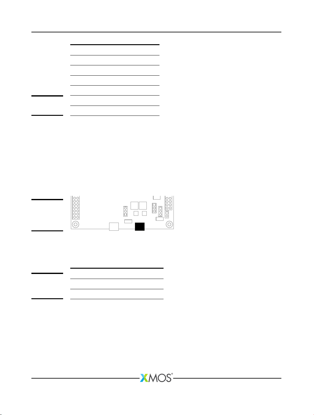
4 Gyroscope and accelerometer
The xCORE-200 explorerKIT provides a BMG160 3-axis gyroscope sensor and an
FXOS8700CQ Digital Sensor (3D Accelerometer (
±
2g/
±
4g/
±
8g) + 3D Magnetome-
ter). These are connected via an I2C interface as described in Figure 7.
XM007647C

xCORE-200 explorerKIT Hardware Manual 7/18
U8
U12
Figure 6:
Gyroscope
and Ac-
celerometer
Pin Port I2C signal
X0D12 P1E SCL
X0D13 P1F SDA
Figure 7:
I2C sensor
interface
5 USB connections
Two micro-USB (B-type) connections are provided:
J16J5
Figure 8:
USB
connectors
Note that J16 must be connected at all times, to provide power to the xCORE-200
explorerKIT. J5 should also be connected when developing USB applications.
6 RGMII connection
An RJ45 connector is available for the development of 10/100/1000 Mbps ethernet
applications.
J4
Figure 9:
10/100/1000
Ethernet
connector
XM007647C

xCORE-200 explorerKIT Hardware Manual 8/18
7 xSYS connector
The xSYS connector is provided to interface to an xTAG debug adapter. The
xTAG debug adapter allows the xTIMEcomposer tools to interrogate the application
running on the xCORE-200 device using the XMOS debugger and the xSCOPE library
which provides non-intrusive program instrumentation.
8 General purpose push-button switches
Two general purpose push-button switches are provided as shown below. When
depressed, the push-buttons create a connection from the IO to GND. Care must be
taken to ensure that this does not cause undesirable behaviour on the xCORE-200
or other components connected through the GPIO headers:
SW1 SW2
Figure 10:
General
purpose
push-button
switches
Each push-button switch is connected to a different IO on the xCORE-200 device as
described in Figure 11:
Pin Port BUTTON
X0D26 P4E0 SW1
X0D27 P4E1 SW2
Figure 11:
General
purpose
push-button
switches
9 Servo connectors
Up to six servos can be connected to the xCORE-200 explorerKIT using the header
sockets provided. Note that it is up to the user to ensure that sufficient supply
power is available to drive the servos.
J12
J10J13J9
J6J11
Figure 12:
Servo
connectors
XM007647C

xCORE-200 explorerKIT Hardware Manual 9/18
Connector Pin 1 Port Pin 2 Pin 3
J8 X0D22 P1G +5V GND
J9 X0D37 P1N +5V GND
J10 X0D35 P1L +5V GND
J11 X0D36 P1M +5V GND
J12 X0D34 P1K +5V GND
J13 X0D23 P1H +5V GND
Figure 13:
GPIO servo
connector
10 User LEDs
xCORE-200 explorerKIT provides two LEDs, a green LED and an RGD LED arranged
as shown below:
D1
D2
Figure 14:
User LEDs
The green LED and each colour terminal of the RGB LED are connected to a different
pin as described in Figure 15:
Pin Port LED
X0D28 P4F0 Green
X0D29 P4F1 RGB (blue term)
X0D30 P4F2 RGB (green term)
X0D31 P4F3 RGB (red term)
Figure 15:
User LEDs
11 QSPI Flash
xCORE-200 explorerKIT provides 1Mbytes of Quad Serial Peripheral Interface (QSPI)
FLASH memory, which is interfaced by the GPIO connections shown in Figure 16:
The xTIMEcomposer tools include the xFLASH utility for programming compiled
programs into the flash memory. xCORE-200 explorerKIT designs may also access
the FLASH memory at run-time by interfacing with the above pins.
XM007647C
xCORE-200 explorerKIT Hardware Manual 10/18
Pin Port QSPI connection
X0D01 P1A CE_n
X0D04 P4B0 IO0
X0D05 P4B1 IO1
X0D06 P4B2 IO2
X0D07 P4B3 IO3
X0D10 P1C SPI_CLK
Figure 16:
QSPI Flash
12 24MHz Crystal Oscillator
The xCORE-200 explorerKIT board is clocked at 24MHz by a crystal oscillator. Each
tile is clocked at 500 MIPS, and all I/O ports are 100MHz.
13 Power connector
xCORE-200 explorerKIT requires a 5V power source input via the micro-USB cable.
J16
Figure 17:
Power
connection
via micro-USB
The voltage is converted by the on-board regulator to the 1V and 3V3 supplies
used by the components. Additional or alternative power sources may use the
power headers provided as shown in Figure 18:
Connector Pin 1 Pin 2 Pin 3
J14 +5V +3.3V GND
J15 +5V +3.3V GND
Figure 18:
Power
connectors
See the Operating requirements section §14 for further information.
14 Operating requirements
A USB 2.0 high-speed compliant cable of less than 3m in length should be used
when operating the xCORE-200 explorerKIT. XMOS cannot guarantee correct opera-
tion of the xCORE-200 explorerKIT should any other cable be used.
XM007647C
Table des matières
Autres manuels XMOS Carte mère


Manuels Carte mère populaires d'autres marques


Telit Wireless Solutions
Telit Wireless Solutions SL869-3DR Manuel utilisateur

Gigabyte
Gigabyte GA-9IVDT Manuel utilisateur

Texas Instruments
Texas Instruments ADS8372EVM Manuel utilisateur

Commell
Commell MS-C73 Manuel utilisateur

IBT Technologies
IBT Technologies MB860 Manuel utilisateur

Nvidia
Nvidia TEGRA DG-04927-001_V01 Manuel utilisateur


