XMOS startKIT XK-STK-A8DEV Manuel utilisateur

Chipsmall Limited consists of a professional team with an average of over 10 year of expertise in the distribution
of electronic components. Based in Hongkong, we have already established firm and mutual-benefit business
relationships with customers from,Europe,America and south Asia,supplying obsolete and hard-to-find components
to meet their specific needs.
With the principle of “Quality Parts,Customers Priority,Honest Operation,and Considerate Service”,our business
mainly focus on the distribution of electronic components. Line cards we deal with include
Microchip,ALPS,ROHM,Xilinx,Pulse,ON,Everlight and Freescale. Main products comprise
IC,Modules,Potentiometer,IC Socket,Relay,Connector.Our parts cover such applications as commercial,industrial,
and automotives areas.
We are looking forward to setting up business relationship with you and hope to provide you with the best service
and solution. Let us make a better world for our industry!
Contact us
Tel: +86-755-8981 8866 Fax: +86-755-8427 6832
Email & Skype: [email protected]om Web: www.chipsmall.com
Address: A1208, Overseas Decoration Building, #122 Zhenhua RD., Futian, Shenzhen, China

startKIT Hardware Manual
IN THIS DOCUMENT
·Features
·xCORE Multicore Microcontroller Device
·PCIe connector and GPIO header (J7)
·Raspberry Pi compatible header and GPIO (J3)
·XMOS Links and GPIO header (J8)
·Touch Sliders
·User LEDs
·SPI Flash
·Push-button switch
·Analog input header
·24MHz Crystal Oscillator
·Power connector
·Operating requirements
·Dimensions
·startKIT Portmap
·startKIT schematics
·Regulatory compliance
startKIT is a low-cost development board for the configurable xCORE multicore
microcontroller products from XMOS. It’s easy to use and provides lots of advanced
features on a small, extremely low cost platform.
xCORE lets you software-configure the interfaces that you need for your system; so
with startKIT you can configure the board to your match your exact requirements.
Its 500MIPS xCORE multicore microcontroller has eight 32bit logical cores that
perform deterministically, making startKIT an ideal platform for functions ranging
from robotics and motion control to networking and digital audio.
startKIT also connects to your Raspberry Pi, allowing you to add real-time I/O
and communication features to this popular computing platform, and to try out
advanced applications for xCORE.
Publication Date: 2014/7/29 Document Number: XM004110C
XMOS © 2014, All Rights Reserved
startKIT Hardware Manual 2/18
1 Features
A block diagram of the startKIT is shown below:
B
A
K
D
E
GHIL
F
F
J
C
C
C
Figure 1:
startKIT block
diagram
It includes the following features:
·A: xCORE Multicore Microcontroller device with integrated debugger
·B: Micro USB connector for debugger/JTAG
·C: PCIe slot for sliceCARD or 1x24 GPIO header
·D: 2x13 header for GPIO and compatible with Raspberry Pi
·E: 1x13 header providing two XMOS Links
·F: Two four-zone cap sense areas
·G: 3x3 grid green LEDs
·H: Two green LEDs
·I: SPI Flash
·J: Push-button switch
·K: 3x2 analog input header
·L: 24MHz Oscillator
XM004110C
startKIT Hardware Manual 3/18
2 xCORE Multicore Microcontroller Device
startKIT is based on a two-tile xCORE device (xCORE-Analog A8-DEV). Tile 0 is
dedicated to the integrated debugger and USB PHY. Tile 1 is user-programmable
providing eight logical cores with a total of 500 MIPS compute. All the digital I/O on
Tile 1 have been brought out to pins providing many combinations of peripherals
to be integrated with the startKIT board.
For information on xCORE tiles and cores see the xCORE Architecture Overview1.
The xCORE-Analog A8-DEV device is only available as part of startKIT, and is
therefore not separately documented. If you are using startKIT as a target platform
and need datasheet-level documentation, you may find it useful to review the
XS1-U16A-128-FB217 Datasheet2.
If you are using startKIT as a development platform and intend to run your final
application on a commercially available single tile device, it may be helpful to
review the XS1-A8A-64-FB96 Datasheet3.
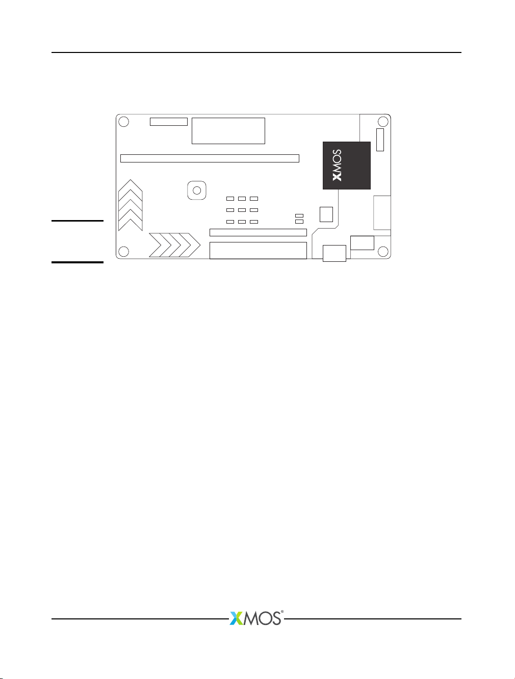
Figure 2:
xCORE-
Analog device
and
integrated
debugger
2.1 Integrated debugger
The integrated debugger and associated components are positioned at one end of
the board. The debugger is accessed by the micro-USB connector connected to the
host PC, allowing the xTIMEcomposer tools to interrogate the application running
on the device using the XMOS debugger and the xSCOPE library which provides
non-intrusive program instrumentation.
See the Power connector section §12 and Operating requirements section §13 for
further information on the USB connector.
1http://www.xmos.com/published/xcore-architecture
2http://www.xmos.com/published/xs1-u16a-128-fb217-datasheet
3http://www.xmos.com/published/xs1-a8a-64-fb96-datasheet
XM004110C
startKIT Hardware Manual 4/18
3 PCIe connector and GPIO header (J7)
The pins of the PCIe connector and the 1x24 GPIO header are mapped to twelve
1-bit ports and three 4-bit ports. The connector and GPIO header are mutually
exclusive. The PCIe connector is suitable for XMOS sliceCARDs such as audio,
Ethernet, IS-BUS.
J6
J7
B1 B18
A18
A1
Figure 3:
PCIe
Connector
The xCORE ports are mapped to the PCIe connector pins as shown in Figure 4:
Port Pin PCIe (top) PCIe (bottom) Pin Port
NC B1 A1 NC
P1F0 X0D13 B2 A2 5V
GND B3 A3 X0D12 P1E0
P1G0 X0D22 B4 A4 X0D23 P1H0
3V3 B5 A5 GND
P4C0 X0D14 B6 A6 X0D20 P4C2
P4C1 X0D15 B7 A7 X0D21 P4C3
GND B8 A8 X0D25 P1J0
P4D0 X0D16 B9 A9 X0D18 P4D2
P1K0 X0D34 B10 A10 GND
P4D1 X0D17 B11 A11 X0D19 P4D3
P1M0 X0D36 B12 A12 X0D32 P4E2
P1N0 X0D37 B13 A13 X0D33 P4E3
P4D3 CLK(DEBUGGER) B14 A14 GND
P1I0 X0D24 B15 A15 X0D35 P1L0
GND B16 A16 RST_N(DEBUGGER)
P1O0 X0D38 B17 A17 X0D26 P4E0
P1P0 X0D39 B18 A18 X0D27 P4E1
Figure 4:
PCIe
connector
XM004110C
startKIT Hardware Manual 5/18
The J6 header provides peripheral support for the PCIe connector as described in
Figure 5
Pin Support
CLK 25 MHz clock, signal generated by debugger
nRST Reset for PCIe slot, signal generated by debugger
5V0 5V power supply
3V3 3V3 power supply
GND Ground
Figure 5:
J6 header
XM004110C
startKIT Hardware Manual 6/18
The GPIO header (J7) provides 24 user configurable GPIO if the PCIe slot is not used
- see Figure 6.
Port Pin GPIO
P1F0 X0D13 1
P1H0 X0D23 2
P1G0 X0D22 3
P1E0 X0D12 4
P4C0 X0D14 5
P4C2 X0D20 6
P4C1 X0D15 7
P4C3 X0D21 8
P4D0 X0D16 9
P1J0 X0D25 10
P1K0 X0D34 11
P4D2 X0D18 12
P4D1 X0D17 13
P4D3 X0D19 14
P1M0 X0D36 15
P4E2 X0D32 16
P1N0 X0D37 17
P4E3 X0D33 18
P1L0 X0D35 19
P1I0 X0D24 20
P1O0 X0D38 21
P4E0 X0D26 22
P1P0 X0D39 23
P4E1 X0D27 24
Figure 6:
J7 Header
GPIO
XM004110C
startKIT Hardware Manual 7/18
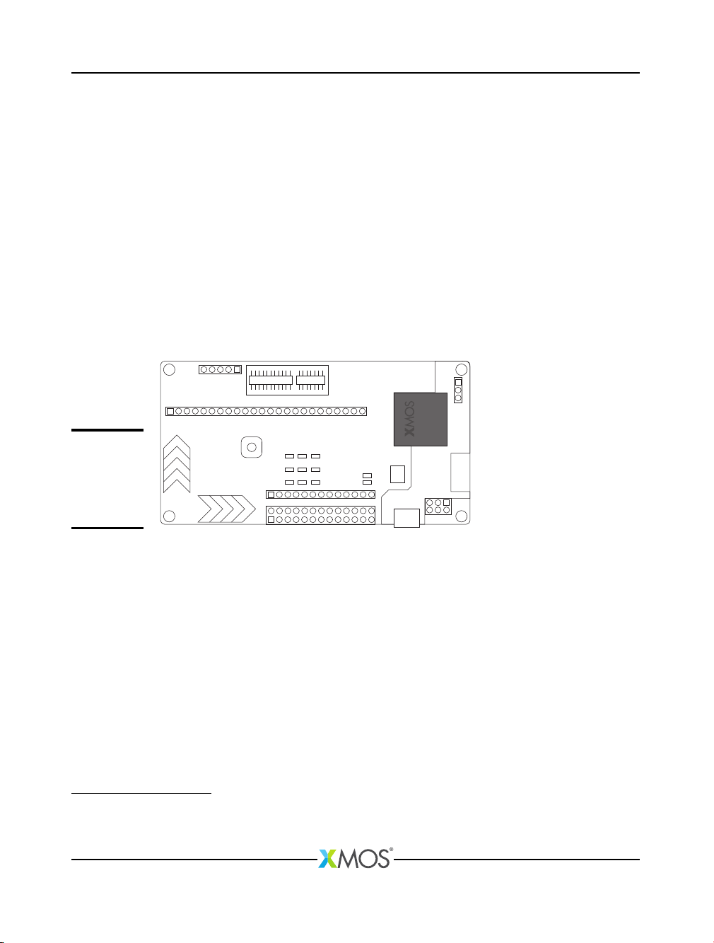
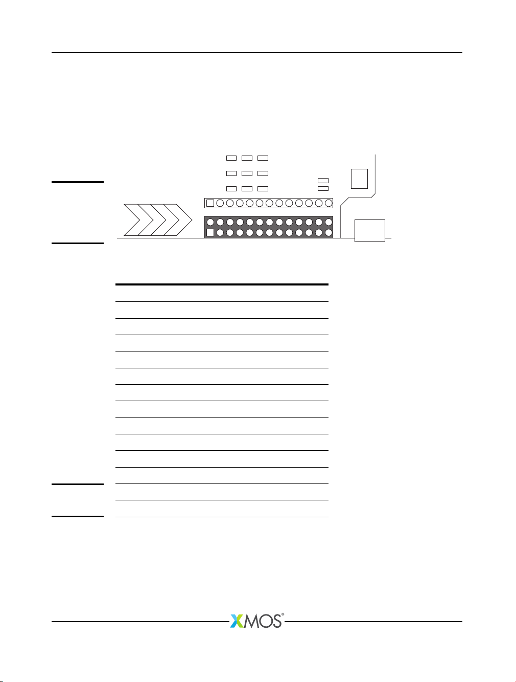
4 Raspberry Pi compatible header and GPIO (J3)
The 2x13 pin 0.1” header is connected to a combination of 1-bit ports and the
32-bit port. It is compatible with a Raspberry Pi connection, or alternatively the
header can be used for user configurable GPIO.
The position of the header on the startKIT board is shown below:
J3
Figure 7:
Raspberry Pi
compatible
header and
GPIO
The xCORE ports are connected to the header as shown in Figure 6:
Port Pin Header IO Pin Port
NC 1 2 NC
P32A0 X0D49 3 4 NC
P32A19 X0D70 5 6 GND
P32A18 X0D69 7 8 X0D68 P32A17
GND 9 10 X0D63 P32A12
P32A10 X0D61 11 12 X0D62 P32A11
P32A9 X0D58 13 14 GND
P32A8 X0D57 15 16 X0D56 P32A7
NC 17 18 NC
P1A0 X0D0 19 20 GND
P1D0 X0D11 21 22 NC
P1C0 X0D10 23 24 X0D51 P32A2
GND 25 26 X0D50 P32A1
Figure 8:
GPIO (J3)
Notes:
·
The compatible Raspberry Pi connections are shown on the back of the startKIT
board.
·
If you use the Raspberry Pi header the LEDs and push button switch are not
available. You can still use the links on the J8 header.
XM004110C
startKIT Hardware Manual 8/18
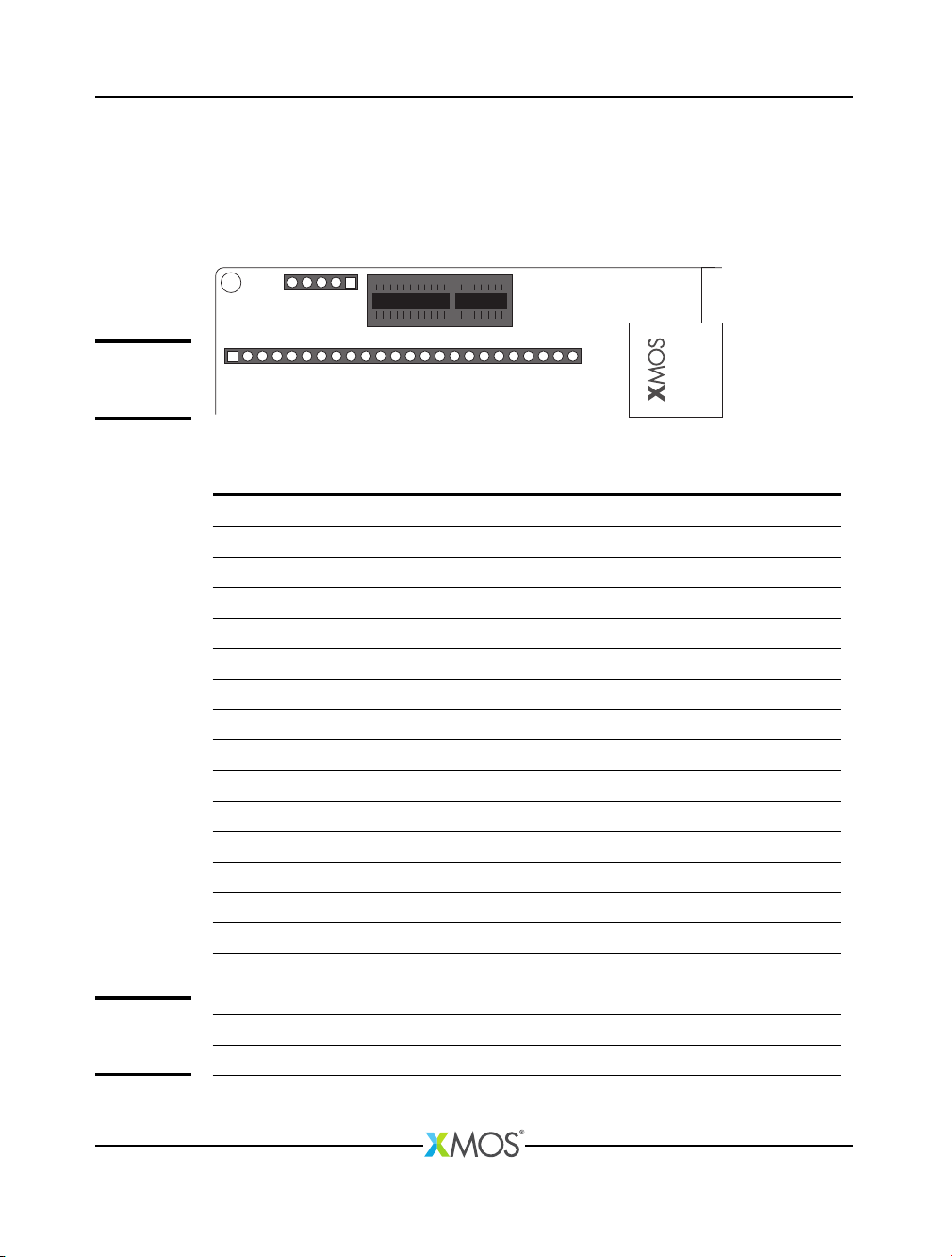
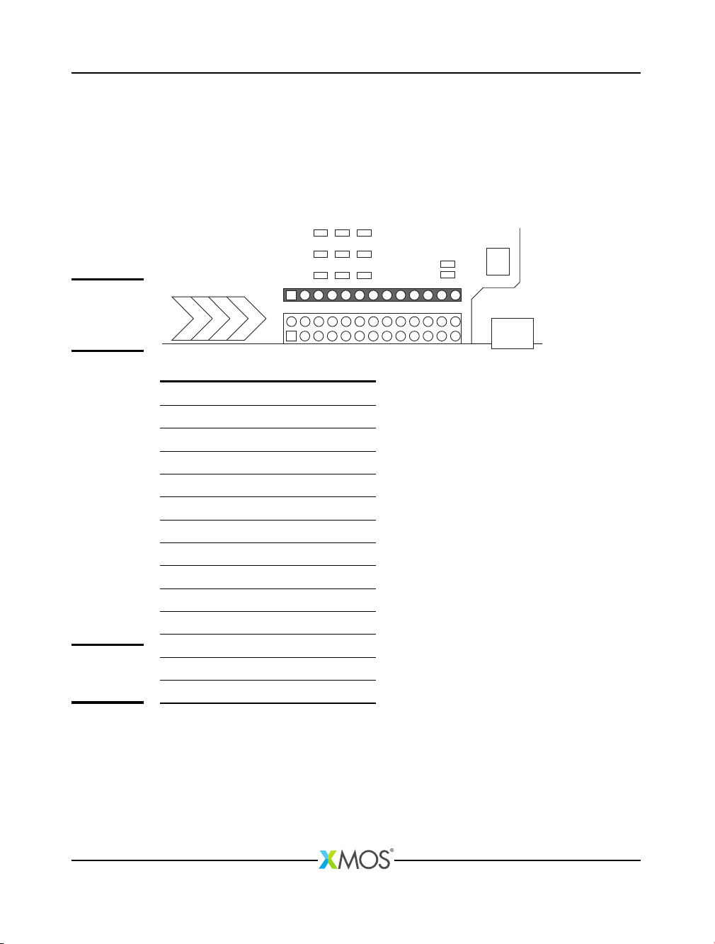
5 XMOS Links and GPIO header (J8)
startKIT has a 1x13 pin GPIO header that includes two 2-wire XMOS Links (Link
C/D), which can be used for connecting multiple startKITs together. Alternatively
the header can be used to provide an additional eight GPIO pins connected to the
32-bit port.
The position of the header on the startKIT board is shown below:
J8
Figure 9:
XMOS Links
and GPIO
header (J8)
Port Pin Position
GND 1
GND 2
P32A3 X0D52 3 - Link C: 1 Out
P32A4 X0D53 4 - Link C: 0 Out
P32A5 X0D54 5 - Link C: 0 In
P32A6 X0D55 6 - Link C: 1 In
P32A13 X0D64 7 - Link D: 1 Out
P32A14 X0D65 8 - Link D: 0 Out
P32A15 X0D66 9 - Link D: 0 In
P32A16 X0D67 10 - Link D: 1 In
GND 11
3V3 12
5V0 13
Figure 10:
J8 header
ports
Note that the XMOS Links connections are shown on the back of the startKIT card.
XM004110C
startKIT Hardware Manual 9/18
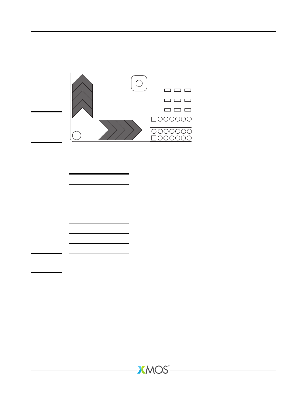
6 Touch Sliders
The startKIT provides two four-zone capacitive touch sensor areas. The layout of
the touch areas is shown below:
SLIDER X
1
2
1 2 3 4
3
4
SLIDER Y
Figure 11:
Capacitive
touch sensor
areas
The touch areas are connected to pins driven by two 4-bit ports as described in
Figure 12:
Port Pin Slider
P4A1 X0D2 X1
P4A2 X0D3 X2
P4A3 X0D8 X3
P4A4 X0D9 X4
P4B1 X0D4 Y1
P4B2 X0D5 Y2
P4B3 X0D6 Y3
P4B4 X0D7 Y4
Figure 12:
Touch sliders
The touch areas must be polled to measure any touch.
XM004110C
Table des matières
Autres manuels XMOS Carte mère


Manuels Carte mère populaires d'autres marques


Telit Wireless Solutions
Telit Wireless Solutions SL869-3DR Manuel utilisateur

Gigabyte
Gigabyte GA-9IVDT Manuel utilisateur

Texas Instruments
Texas Instruments ADS8372EVM Manuel utilisateur

Commell
Commell MS-C73 Manuel utilisateur

IBT Technologies
IBT Technologies MB860 Manuel utilisateur

Nvidia
Nvidia TEGRA DG-04927-001_V01 Manuel utilisateur


