Wombot Drafter Manuel utilisateur

Controlled Document – Wombot Drafter Kit Manual V1.3 1 | P a g e
Personal 3D Printer
Kit Assembly Manual

Controlled Document – Wombot Drafter Kit Manual V1.3 2 | P a g e
Contents of This Manual
Section Page
Introduction 3
Tools Required 4
How to use this Manual 5
Section Assembly Sequence Page
Part 1 Printer Frame 6
Part 2 Y Axis Assembly & Heated Bed 12
Part 3 Extruder Module 22
Part 4 Z Axis Assembly 33
Part 5 Motherboard Enclosure & Saddles 35
Part 6 X Axis Assembly 36
Part 7 LCD Control Module 46
Part 8 Wiring 47
Part 9 Finishing Touches 60
Part 10 Powering Up & Initial Tests 65
Part 11 Component Listing / B.o.M 67
Part 12 Recommended Spare Parts List 70

Controlled Document – Wombot Drafter Kit Manual V1.3 3 | P a g e
Introduction
Thank you for purchasing the Wombot Drafter Kit. We hope it brings you many hours of
learning, enjoyment and reliable service. Please read this assembly manual fully before
beginning assembly of your Drafter and ensure that you understand every step of the
assembly process. Every care has been taken to ensure that you have a complete kit of
components which will enable to you complete assemby however should you find anything
missing or damaged in transit, please contact us at suppor[email protected]m.au to request
replacements. Please note that support for the Wombot Drafter Kit is limited to this
instructional manual, email services and online tutorials. Because of the nature of this
product, telephone support is not practical.
Health & Safety
Your health and safety are important to us and should be your top priority always. Please
take care while assembling your kit, take your time and be careful when using hand tools
and while handling the components used to assemble your printer. Personal safety is
ultimately your responsibility. Please ensure that your workspace is clean, tidy and free of any
safety hazards prior to beginning the assembly of your Wombot Drafter. Please take care
when using sharp tools or handling aluminium extrusion pieces – they can have sharp edges.
During use, please also keep in mind that 3D Printers have two main areas which can reach
high temperatures – the heated bed which can sustain 110 degrees Celsius, and the
Nozzle/Hot End/Extruder, which is designed to operate at a maximum of 250 degrees Celsius.
Instant and serious burns can result from contact with the skin. Please also ensure that your
Drafter is situated in a safe place away from the reach of children and household pets during
operation. Once you have completed the assembly of your Wombot Drafter, please also
familiarise yourself with the User Manual before attempting to print for the first time as it
contains useful information on how to calibrate and operate your Drafter as well as
troubleshooting information.
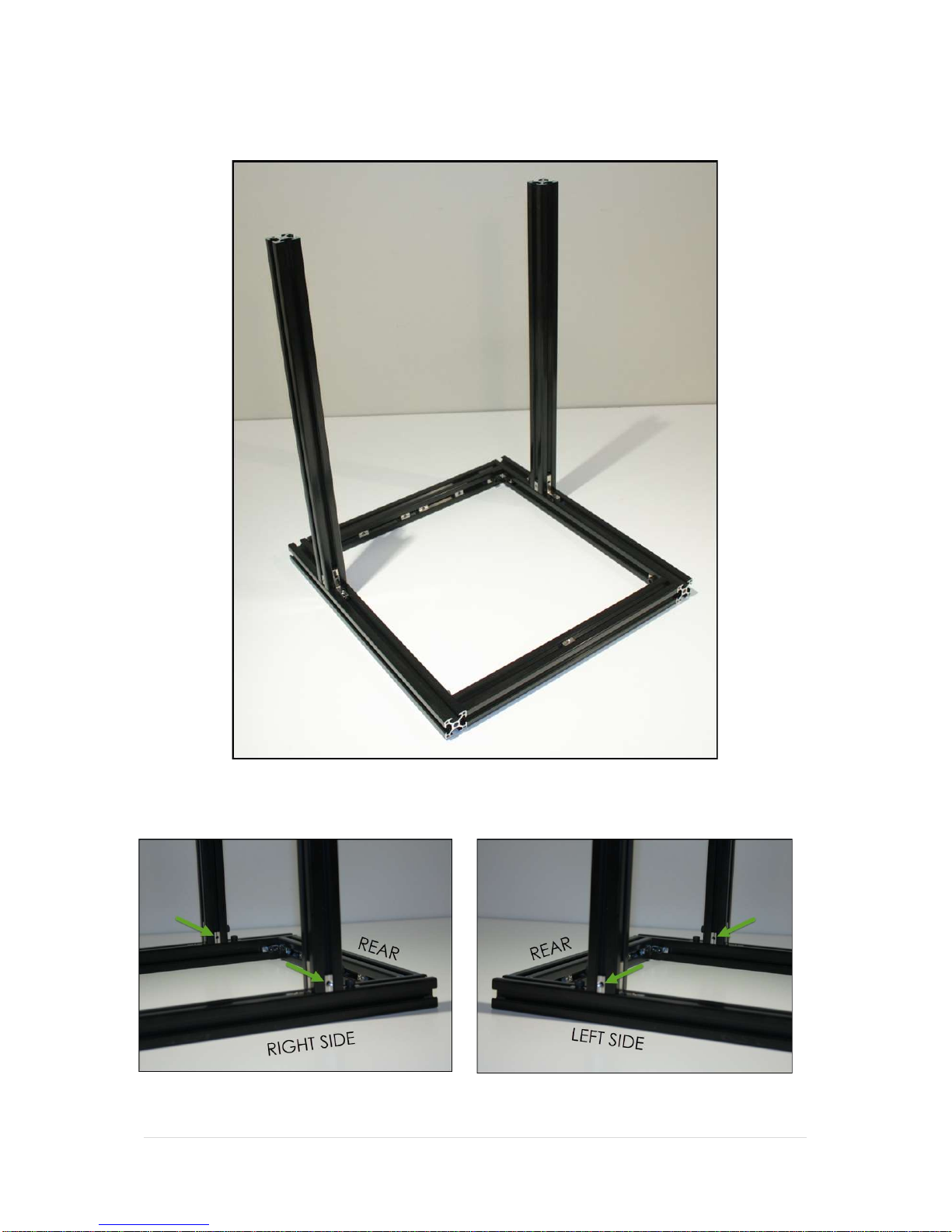
Assembly Sequence Overview
The assembly of your Wombot Drafter needs to take place in the sequence outlined in this
manual so that each step is completed correctly and in order. This will allow you to get your
kit assembled in the shortest possible time and reduce the chances that you will have to
disassemble the printer later to repeat an important missed step or critical component. This
applies especially to the sliding nuts used throughout the frame assembly because once
assembled, sliding nuts cannot be fitted later without disassembling the whole frame.
Please take the time to read each step carefully before beginning assembly to make sure
that you understand the requirements of each module and that the required components
have been laid out on your workspace along with the appropriate tools.

Controlled Document – Wombot Drafter Kit Manual V1.3 4 | P a g e
Tools Required to complete your Wombot Drafter
All components required to complete assembly are included with your Wombot Drafter Kit.
You will also require some basic hand tools and equipment as follows:

Controlled Document – Wombot Drafter Kit Manual V1.3 5 | P a g e
How to use this manual
This manual contains a great deal of detailed information about how to assemble your
Wombot Drafter and about 3D Printers and 3D Printing in general. It is laid out in a logical,
methodical order with written descriptions in non-technical terms and is fully illustrated with
high quality colour images so that you can see exactly what you are aiming for with each
step. Please read this manual from front to back before commencing assembly to familiarize
yourself with each section of the build and the components required.
3D Printers are a fantastic way of bringing to life your ideas and creative inspirations as well
as an extremely useful tool for creating practical everyday objects, from that hard-to-get
replacement part on your clothes dryer to a fully functional radio-controlled quad-copter
frame, however they are extremely mechanically dependent on measurements being
correct during assembly and require a great deal of attention to detail in order to achieve
optimal results. For this reason, we have highlighted areas of critical importance, either
because there is a safety concern, a particular way of doing something, or a helpful tip to
assist in assembly.
These items of importance are highlighted throughout this manual as follows:
ATTENTION: Pay Particular Attention during assembly.
Helpful Tip: Suggestions and Instructions to assist you in the correct
assembly of your Drafter to save time and avoid possible problems
later.
CAUTION: Hot Surface when in use – Please exercise extreme care.
CAUTION: Pinch Hazzard – do not touch while in use.
PARALLEL / PERPENDICULAR: Please take extra special care to make
sure that the indicated components are fitted parallel or
perpendicular to one another as required.

Controlled Document – Wombot Drafter Kit Manual V1.3 6 | P a g e
Part 1 - Printer Frame
In your kit of parts, locate the following items:
ITEM DESCRIPTION QTY
1 3030 INTERNAL R/A BRACKET 10
2 CHASSIS RAIL/GANTRY RAIL 3030 BLACK x 340mm 3
3 LEFT/RIGHT CHASSIS RAIL 3030 BLACK x 410mm 2
4 M6 GRUB SCREW 4
5 M6 x 10MM HEX HEAD CAP SCREW 16
6 SLIDING NUT M5 SYSTEM 30 16
7 VERTICAL RAIL 3030 BLACK x 470mm 2
Prepare the Internal Right-Angle Brackets as per the following Images.
x2 PIECES x8 PIECES
Lay out your Extrusions on a flat surface and assemble your pre-prepared brackets as per the
following images. Tighten the Screws and Grub screws making sure that the vertical rail is
perpendicular to the base rail:
Repeat this process so that you have two identical side frame assemblies.
Set these two frames aside for the moment.

Controlled Document – Wombot Drafter Kit Manual V1.3 7 | P a g e
Lay out your remaining 3 extrusion pieces and load the Sliding Nuts as per the following
images:

Controlled Document – Wombot Drafter Kit Manual V1.3 8 | P a g e
Arrange your frame rails as per the attached images ready to be slotted together and
fasteners tightened:
VIEW FROM FRONT OF FRAME
VIEW FROM REAR OF FRAME

Controlled Document – Wombot Drafter Kit Manual V1.3 9 | P a g e
Slide the internal corner brackets into the ends of the extrusions and slot the frame together
so that it matches the following image and gently tighten all the bolts in place:
Now slide the remaining 4 M5 Sliding nuts into the sides of the vertical rails as indicated by the
green arrows in the following images:

Controlled Document – Wombot Drafter Kit Manual V1.3 10 |
P a g e
Complete the frame assembly by fitting the final piece of 3030 Extrusion – the Top Gantry Rail
to the top of the frame using the last two internal brackets as per the following images:
When fastening the Top Gantry Rail in place, please make sure that the two vertical rails are
parallel to one another. This can be achieved by measuring the distance between them at
the base, and comparing it to the distance at the top. They should be the same. If they are
not, loosen the appropriate bolts on the internal right angle brackets and adjust as required
to achieve the same measurement between the vertical rails, from top to bottom.
Table des matières


