IST-2293.KM01.01 Istruzione / User’s Manual / Manuel d’utilisation Pag.4/9
TECNOCONTROL S.r.l. Via Miglioli 47 SEGRATE ( MI ) Tel: 02/26 92 28 90 Fax: 02/21 33 734
IMPORTANTE: La prova, deve essere eseguita con estrema attenzione e da personale autorizzato e addestrato, in
quanto vengono attivate le uscite (relè) provocando l’attivazione dei dispositivi d’allarme collegati. Il pulsante di TE T
è disabilitato se uno o più ingressi sono oltre il 1 %LEL.
Verifica funzionamento elettrico della centralina, tenere premuto il pulsante TEST per 5 secondi, si avvierà la
procedura di test, indicata delle scritte sul display. In sequenza si illumineranno i 3 Led e si attiveranno i relè FAULT
e ALARM 1, e ALARM 2. Poi dopo 5 secondi la centralina torna automaticamente in funzionamento normale.
EN
DESCRIPTION
The SE293K is a Control unit for heating plants or environments to be protected from possible gas leaks, which can
be connected up to 3 remote catalytic detectors for flammable gases. It can be connected to the following detectors:
• The SE192KM and SE193KM or SE182KM should be used in plants using Methane.
• The SE192KG and Se193KG or SE182KG should be used in plants using LPG.
The SE293K is for wall mounting and the protection code is IP65. It is mains powered at 11 ÷24 VAC / 5 ÷6 Hz
but can also be connected either to an external 24VDC power supply (e.g. power supply unit with two 12V-7A/h
buffer batteries, our mod. PS18 /24VDC).
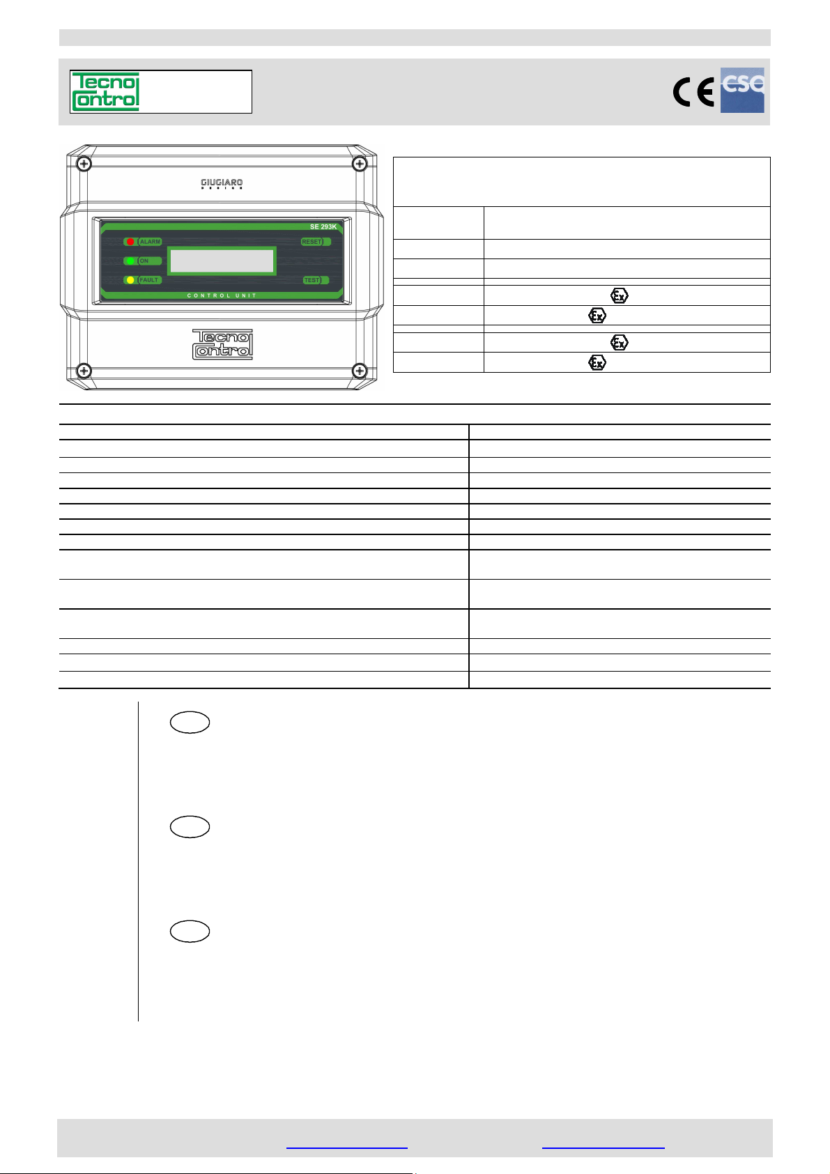
On the front plate there are, three LED that indicate the operating status, the display, which shows the gas concen-
tration detected by each remote detector and two function keys (TEST and RESET).
The control unit has two alarm levels with sealed relay outputs (ALARM1 and ALARM2), with tension free changeover
contacts. Furthermore, it is also present another output relay (FAULT) in positive safety for fault situations. The con-
trol unit has two auxiliary inputs. AUX1 to connect NO contact devices such as a manual Button. AUX2 is the control
input for our Manual NC Resetting Valve with positioning sensor.
In Fig.1 a connection example with 3 remote gas detectors, siren, manual reset solenoid valve and manual button.
OPERATIONAL DESCRIPTION
Power on: all times the control unit is powered, the display shows the name of the manufacturer, the model and the
firmware version (eg. Tecnocontrol srl / SE293K v.1.00).
Language: Then, on the display, the choice of available languages (eg EN-EN-FR) appears, pressing the RESET
key will change the language, pressing the TEST key confirms the choice. If you do not make a choice within 1
seconds, the program continues automatically maintaining the last selected language.
WARNING: the language choice, always appears at each power on, but after 10 seconds the program will automatically continue maintai-
ning the last selected language.
Info: then, always appear in sequence 3 screens with configuration set reminders via the Dip-Switch: SCALE OF
MEASURE / ALARMS THRESHOLD / ENABLED DETECTORS. Then the program continues automatically.
Preheating: when the control unit is powered, the preheating phase begins, the display shows the 6 seconds
countdown and the yellow LED flashes.
Normal operating: at the end of the preheating, the display shows the value of the gas concentration and the sta-
tus of the remote detectors.
The Green LED lights up to indicate the normal operation and the presence of power.
The Red LED (ALARM): lights up flashing, if the gas concentration exceeds the 1st alarm threshold (configurable to
1 or 15% LEL) and within 5 seconds the ALARM 1 relay will activate. This relay is normally used as a prealarm us-
ing a siren (Our model SE30 A when powered by 230VAC or the model SE30 B when powered by 24VDC).
The display shows the channel, in alarm, alternately displaying the value and writing AL1.
The Red LED (ALARM): lights up if the gas concentration exceeds the 2nd alarm threshold (2 % LEL); if the gas
persists, after 3 seconds, the ALARM 2 relay will activate. It is configurable in positive (normally energized) or nega-
tive logic. It is normally used to stop the gas through the manual reset solenoid valve and/or the interruption of the
electrical power at the plant only, the control unit must remain powered.
The display shows the channel, in alarm, alternately displaying the value and writing AL2.
If the manual button is connected to the AUX1 input, when pressed, the ALARM 2 relay will be activated.
If it has been installed a manual reset solenoid valve N.C. with magnetic sensor (mod. VR420÷VR480) connected to AUX2 input, in case
the valve has not closed the gas, the yellow L D and the FAULT Relay will activate (see FAULT section).
“RESET” Key: this key has two functions:
SILENCING : when the key is pressed, the Red LED flashes and the ALARM 1 relay connected to the Siren is si-
lenced, but after 12 seconds, it will automatically reactivate.
RESET: if the 2nd alarm threshold is exceeded, the ALARM 2 relay remains activated (latched), even if the gas con-
centration decreases (because the valve is closed, if installed). The display shows the channel, in alarm, alternate-
ly displaying the value and writing AL2. After having eliminated the cause of the alarm, to restore the normal work-
ing conditions press the RE ET key. For safety, the key cannot operate when the remote detector is detecting gas.
Faults: The control unit indicates a fault condition of a remote gas detector. The display shows FLT (FAULT) on the
faulty channel, turns on the yellow LED, and activates the FAULT relay that is normally energized with voltage-free
changeover contacts, if necessary, it can be used both to signal remotely an occurred damage and to signal the ab-
sence of power to the instrument. Fault signals must not be connected to the alarm signals.
Manual reset solenoid valve NC with magneti sensor failure: this situation appears ONLY when is installed an electro
valve with magnetic sensor; connected to AUX2 imput. If the valve does not close the gas, (with the ALARM 2 relay in alarm), the magnetic
sensor signals to the Control unit the malfunction. If the problem will be resolved, (the solenoid valve is closed) the fault condition (yellow
L D on and FAULT relay activated) will be canceled by pressing the RE ET key. If, however, by pressing the RE ET key, the alarm ends,