Superior Xtreme Series Manuel utilisateur

Xtreme ™ Series
Touchscreen Manual
Software version 4.2.XX
Why Would You Go Anywhere Else?
Superior PAPER HANDLING SOLUTIONS
Have this information ready when calling in about your equipment:
Model: Serial #:
PLC firmware version: HMI firmware version:
Warranty Start Date:
© Superior Paper Handling Solutions, Inc. All rights reserved.
Illustrations in this guide are for reference only and may depict optional features that are available
at additional costs.
Superior Paper Handling Solutions, Inc.
14414 21st Avenue North
Plymouth, Minnesota 55447 – USA
Tel. 763-546-9140
Fax. 763-546-8883
Email. [email protected]
Web. www.Superior-PHS.com

CONTENTS
SCREEN LAYOUT .......................................................................................................... 3
MECHANICAL PUSH BUTTONS .................................................................................... 4
POWER UP SCREEN ..................................................................................................... 4
RUN SCREEN ................................................................................................................. 5
5_JOB SETUP SCREEN ..................................................................................... 6
1_SETUP 1 SCREEN ...................................................................................................... 7
2_SETUP 2 SCREEN ...................................................................................................... 8
3_SETUP 3 SCREEN ...................................................................................................... 9
4_COUNTERS SCREEN ................................................................................................. 9
6_DROPPER SELECT SCREEN .................................................................................. 10
BD/RD SELECT SCREEN ................................................................................. 10
MDRD SELECT SCREEN ................................................................................ 11
SD DROPPER SELECT SCREEN ................................................................... 12
2 STAGE DROPPER SELECT SCREEN ......................................................... 13
7_INPUTS 1 .................................................................................................................. 14
8_INPUTS 2 .................................................................................................................. 14
9_OUTPUTS 1............................................................................................................... 14
10_OUTPUTS 2............................................................................................................. 14
MESSAGE and ERROR DISPLAYS .............................................................................. 15
OPERATORS NOTE PAGE
page 2

RUN COUNTER DROPPER INPUTS/OUTPUTS SETUP
POWER UP
Brings you to the POWER UP Screen
Brings you to the RUN Screen
Brings you to the previous numbered Screen
Brings you to the next numbered Screen
Brings you back to the main
numbered Screen you started from
BELOW COMMANDS WORK WITHIN THE
NUMBERED SCREENS 1-10:
© 2005-2015 Superior-PHS
Why Would You Go Anywhere Else?
page 3

© 2005-2015 Superior-PHS
Superior PAPER HANDLING SOLUTIONS
HMI and PLC firmware versions
HOME [POWER UP SCREEN]
RUN: Takes operator directly to Run Screen
COUNTER: Takes operator directly to 4-Counters Screen
DROPPER: Takes operator directly to 6-Dropper Select Screen
INPUTS/OUTPUTS: Takes operator directly to 7-Inputs 1 Screen
SETUP: Takes operator directly to1-Setup 1 Screen
NOTE: All settings from previous power down will be retained
page 4
Stop/Reset Button If an error occurs this push button will illuminate.
It will also light when the stop is used to stop the feeder. Clear all errors if
present and push this button to move the feeder to a Ready stage.
Cycle Button If the feeder is Ready than this push button will illuminate.
From here pressing the button will command a start cycle.
Jog Button The feeder will advanced when the Jog button is pressed.
The feeder will continuously run when the jog button is activated. This
option is typically used when setting up product in the feeder or clearing
any product under the Separator. While holding down the Jog button, you
can adjust the Separator and feed product until the product feeds consistently.
MECHANICAL FRONT PANEL PUSH BUTTONS

Why Would You Go Anywhere Else?
© 2005-2015 Superior-PHS page 5
RUN
JOB SET: Takes operator directly to 5-Job Set Screen
MODE [LOCAL or SYSTEM]: Local Mode is the standard
setting. Push to toggle between System and Local Mode.
To run the feeder in a stand alone operation this
must show Local Mode. (Green displayed)
CONTINUOUS MODE: Display only. If the feeder is in
Continuous Mode this display will appear. (Green displayed)
CYCLE SPEED: Allows user to set feeder speed. 100 is
equal to maximum speed.
RESET COUNT: Pressing this button will reset the Actual Count display. If the feeder has stopped in the
middle of completing a Batch, pressing this reset will start the batch count over.
BATCH SIZE: Pressing this button will allow a user to set the batch size.
[KEYBOARD ENTRY-MIN/MAX WITHIN KEYBOARD DISPLAY ]
ACTUAL COUNT: Display only. Displays the count as the feeder is running. It will count up to your batch
size and reset to zero when the batch is complete. If the feeder errors or stops before the batch cycle
completes, this number will reflect what has been counted. Starting the feeder again will finish the batch.
NOTE: If using the EXT I/O to remotely STOP, RESET and CYCLE the feeder; Upon an error
or remote stop, the Actual Count will always reset to zero and not retain the partial batch. If required to retain
the partial batch, then remotely PAUSE/RESUME the feeder through the EXT I/O.

© 2005-2015 Superior-PHS
Superior PAPER HANDLING SOLUTIONS
page 6
NOTE: When the Job Set is turned on and the Total Count reaches zero a display will appear
stating the Job Set is complete. In order to initiate another batch cycle you must turn the Job Set off.
5 - JOB SET
DROPPER: Takes operator directly to 6-Dropper Select
Screen
TOTAL COUNT: Enter the Job size. [KEYBOARD ENTRY
-MIN/MAX WITHIN KEYBOARD DISPLAY ]
JOB SET ON/OFF: When using the Job Set function, you
will be able to set a Total Count that will stop the feeder
when reached (i.e. while batching 50 piece sets, you only
5000 sheets batched out)
NOTE: If Total Count is at zero when Job Set is turned on
it will display Job Complete. Enter count first
ACTUAL COUNT: Display only. Does not function in Continuous Mode. This will display the Actual Count
where the feeder is at within a batch. Mirrored display to the Actual Count from the Run Screen.
BATCH COUNT: Display Only. Does not function in Continuous Mode. This will display the number of
batches completed by the feeder. The Reset button allows this field to clear to zero when pressed.
NOTE: The Run Screen does not display accumulation of Batch Counts. Because this field doesn’t require
the Job Set to be turned on, acquiring Batch Counts can be retrieved in this 5 - Job Set Screen even when
the Job Set function is not being used. The 4 - Counters Screen also displays the Batch Count field. They
are also mirrored displays and the Reset buttons from either screen will zero it.
COUNT to TOTAL : Display only. Displays the quantity left until the Job Set is complete.S

Why Would You Go Anywhere Else?
© 2005-2015 Superior-PHS page 7
1 - SETUP 1
TRIGGER DELAY: Enter the delay time in seconds
[KEYBOARD ENTRY-MIN/MAX WITHIN KEYBOARD
DISPLAY ] Used only with trigger sensor or external
CYCLE input.
SKIP FLIGHT: Enter the number of skips per trigger.
[KEYBOARD ENTRY-MIN/MAX WITHIN KEYBOARD
DISPLAY ] Used to skip the feeder from firing every
on every trigger. (i.e every third pocket)
SLOW START or STOP function: The next three functions control the settings with regards to
setting a slower speed when starting or stopping the feeder. At high speeds this will assist
controlling product to stop consistently and also limit the possible skewing of product as the
feeder advances at startup to a high speed.
SLOW STOP COUNT: Set how many pieces at the end of a batch will run at the slow speed.
[KEYBOARD ENTRY-MIN/MAX WITHIN KEYBOARD DISPLAY ]
SLOW START COUNT: Set how many pieces at the beginning of a batch will run at the slow speed.
[KEYBOARD ENTRY-MIN/MAX WITHIN KEYBOARD DISPLAY ]
NOTE: The slow function is turned ON when a value of 1 or greater is recorded at either two of the count
buttons above. In order to not use the slow function, a value of zero must be recorded in those settings.
CONTINUOUS MODE: Set ON/OFF from here. The Run Screen has a display and this button will
illuminate green when the condition is ON.
PAUSE RESUME: Set ON/OFF from here. The Pause/Resume function is used to automatically keep
cycling the feeder with a period of time between batches. This button will illuminate green when the
condition is ON.
PAUSE RESUME TIME: Enter the time value in seconds. This represents the time between the batch
cycles. [KEYBOARD ENTRY-MIN/MAX WITHIN KEYBOARD DISPLAY ]
SLOW SPEED : Set the speed of the feeder when either the Slow Start or Slow Stop is activated.
[KEYBOARD ENTRY-MIN/MAX WITHIN KEYBOARD DISPLAY ] Recommended to be less than half
the speed recorded in Cycle Speed from the Run Screen.
© 2005-2015 Superior-PHS
Superior PAPER HANDLING SOLUTIONS
page 8
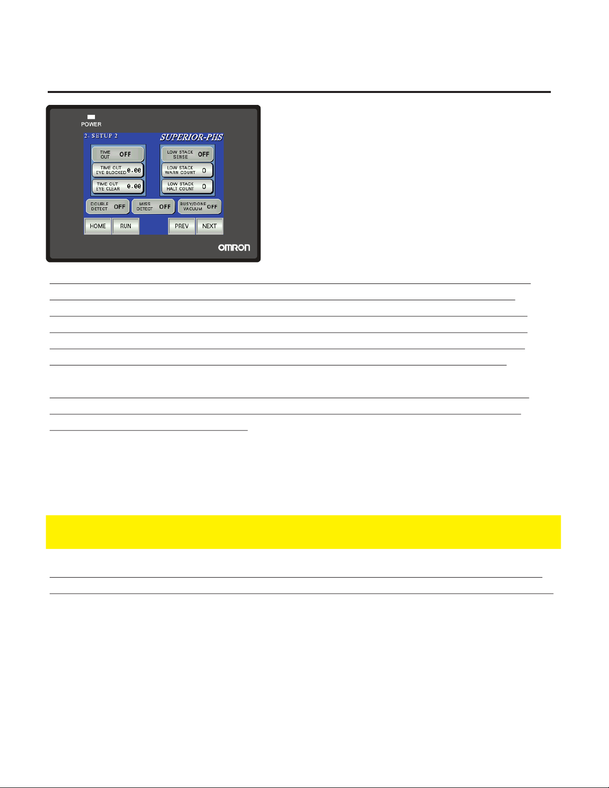
2 - SETUP 2
DOUBLE DETECT: Allows user to turn ON/OFF the
Double Detect. Green illumination when ON.
MISS DETECT: Allows user to turn ON/OFF the Miss
Detect. This function monitors that the batch cycle
has completed before receiving another trigger or
remote START. Green illumination when ON
BUSY/DONE VACUUM: Allows user to turn ON/OFF
the Busy/Done or Vacuum function. Read below for
explanation of functions. Green illumination when ON
BUSY/DONE or VACUUM function: There is a particular I/O point in the Ext Interface that will
change its state with regards to whether the motor on the feeder is running or not. Thus a
system controller could monitor the feeder and know when it has completed its batch cycle.
The Vacuum application is considered when an optional venturi vacuum setup is purchased
with the feeder. This allows the vacuum to only operate when the feeder is running. EITHER
one condition or the other is used as a scenario. Both situations use the same I/O point.
TIME OUT function: The next three functions control the settings with regards to setting the
Time Out function. This is used to monitor the sheet sensor for clear and block conditions.
(Feeder empty or Jammed conditions)
TIME OUT EYE CLEAR: Enter the time in seconds. An error will occur if the sheet sensor stays open
the duration of time set. [KEYBOARD ENTRY-MIN/MAX WITHIN KEYBOARD DISPLAY ]
TIME OUT EYE BLOCKED: Enter the time in seconds. An error will occur if the sheet sensor stays
blocked the duration of time set. [KEYBOARD ENTRY-MIN/MAX WITHIN KEYBOARD DISPLAY ]
NOTE: The time set for blocked has to be large enough to allow one piece to advance completely
through the sheet sensor. This may have to set bigger for large product running at slow cycle speeds.
LOW STACK function: The next three functions control the settings with regards to setting the
Low Stack function. This function is only used if the feeder was purchased with a Low Stack eye.
LOW STACK WARN: Set how many pieces once the Low Stack eye clears to when the warning amber
light will flash (Requires purchase of light tower with feeder) [KEYBOARD ENTRY-MIN/MAX WITHIN
KEYBOARD DISPLAY ]
LOW STACK HALT: Set how many pieces once the Low Stack eye clears to when the feeder will stop.
Product must be filled again to cycle the feeder. [KEYBOARD ENTRY-MIN/MAX WITHIN KEYBOARD
DISPLAY ]
TIME OUT: Allows the user to turn ON/OFF the Time Out function
LOW STACK : Allows the user to turn ON/OFF the Low Stack function. Green illumination when ON
. Green illumination when ON

Why Would You Go Anywhere Else?
© 2005-2015 Superior-PHS page 9
3 - SETUP 3
and cycles at the speeds programmed below.
TAMPER RETURN DELAY: Enter the return time in seconds
for the actuator arm. [KEYBOARD ENTRY-MIN/MAX
WITHIN KEYBOARD DISPLAY ]
TAMPER EXTEND DELAY: Enter the extend time in seconds
for the actuator arm. [KEYBOARD ENTRY-MIN/MAX
WITHIN KEYBOARD DISPLAY ]
NOTE: General settings will have these extending and
returning times around .2-.5 seconds, dependent on the
air volume and tamping speed requirements.
MANUAL CYCLE: Manually activates the wedge tamper
WEDGE TAMPING function: This function along with the mechanical assembly will tap the
product while stacked in the hopper. This assists in funneling the product down into the separator
assembly for better performance.
# OF SHEETS BETWEEN TAMPS: Set how many pieces will run between tamping cycles.
[KEYBOARD ENTRY-MIN/MAX WITHIN KEYBOARD DISPLAY ]
TAMPS # OF TIMES : Set how many times the tamper will extend and return during its tamping cycle.
[KEYBOARD ENTRY-MIN/MAX WITHIN KEYBOARD DISPLAY ]
TAMPER DISABLED : Turn the Tamper ON/OFF. Green Illuminate when the function is enabled.
NOTE: If you did not purchase a Wedge Tamper, disregard this setup page and leave it disabled.
4 - COUNTERS
products through the sheet counter. RESET button sets
to zero
BATCH COUNTER: Display only. Counts the number of
batches completed through the sheet counter. RESET
button sets to zero
TOTAL PIECE COUNTER: Display only. Counts the
number of products through the sheet counter.
NOTE: This Display is not resettable. It will reflect the
number of pieces through the feeder at any given time
PIECE COUNTER: Display only. Counts the number of

© 2005-2015 Superior-PHS
Superior PAPER HANDLING SOLUTIONS
page 10
6 - DROPPER SELECT
BD/RD DROPPER: Allows user to turn ON/OFF. Green
illumination when ON.
BD/RD DROPPER SETUP: Takes you to Setup page.
SD DROPPER: Allows user to turn ON/OFF. Green
illumination when ON.
SD DROPPER SETUP: Takes you to Setup page.
MDRD DROPPER: Allows user to turn ON/OFF. Green
illumination when ON.
MDRD SETUP: Takes you to Setup page.
2 STAGE SETUP: Takes you to Setup page.
NOTE: If you did not purchase a dropper, disregard this setup page and leave all OFF.
NOTE: Only one Dropper can be ON at one time.
BD/RD SETUP
BACK: Takes user back to 6 - Dropper Select Screen
DROPPER EXTEND DELAY: Sets the time in seconds
the period the dropper stays open. [KEYBOARD ENTRY
-MIN/MAX WITHIN KEYBOARD DISPLAY ]
FEEDER DELAY: Sets the time in seconds the feeder
will delay before feeding the next batch. [KEYBOARD
ENTRY-MIN/MAX WITHIN KEYBOARD DISPLAY ]
MANUAL CYCLE: Cycles the dropper once.
Table des matières
Autres manuels Superior écran tactile

Manuels écran tactile populaires d'autres marques

Elecro Engineering
Elecro Engineering Poolsmart Plus Instructions d'installation

Johnson Controls
Johnson Controls IQ4 HUB Manuel utilisateur

Elo TouchSystems
Elo TouchSystems ET2270L Manuel utilisateur

Elo TouchSystems
Elo TouchSystems ET1002L Manuel utilisateur

Elo TouchSystems
Elo TouchSystems 3201L Manuel utilisateur

Duratec
Duratec S15 Manuel utilisateur


