sparkfun DEV-16829 Manuel utilisateur

MicroMod Data Logging Carrier Board Hookup Guide
Introduction
The MicroMod Data Logging Carrier Board is similar the SparkFun Logomatic to offer users a dedicated data
logging board but adds the ability for you to pick a MicroMod Processor Board to customize it for your next data
logger project. The Data Logging Carrier board was designed specifically for low power control and sensor data
harvesting with the MicroMod ecosystem.
The Data Logging Carrier Board allows you to control power to both the Qwiic connector on the board as well as a
dedicated power pin for non-Qwiic peripherals such as serial UART or SPI devices so you can pick and choose
when to power the peripherals you are monitoring the data from. It also features a charging circuit for single-cell
Lithium-ion batteries along with an RTC battery-backup circuit to maintain power for a real-time clock circuit on
your Processor Board.
Required Materials
Like all of our MicroMod Carrier Boards, there is no processor included but instead you can plug in a Processor
Board of your choice to the MicroMod M.2 connector on the carrier. Below are a few options to choose for your
processor:
SparkFun MicroMod Data Logging Carrier Board
DEV-16829

You'll also need a USB-C cable to connect the Carrier Board to your computer to program your Processor and for
serial USB communication. If you want to add some Qwiic breakouts to your MicroMod project you'll want at least
one Qwiic cable to connect it all together. Below are some options for both of those cables:
SparkFun MicroMod Artemis Processor
DEV-16401
SparkFun MicroMod ESP32 Processor
WRL-16781
SparkFun MicroMod SAMD51 Processor
DEV-16791
SparkFun Qwiic Cable Kit
KIT-15081
Qwiic Cable - 100mm
PRT-14427

Along with a Processor Board, the pertinent cables and sensors or other items you intend to log the data from,
you'll need a microSD card. Lastly, if you would like to have your MicroMod Data Logging project be battery
powered, you'll want a single-cell Lithium-ion battery. Below are a few options for both of those accessories:
Suggested Reading
The SparkFun MicroMod ecosystem is designed to allow users to customize their project to their needs. Do you
want to send your weather data via a wireless signal (eg. Bluetooth or WiFi)? There's a MicroMod processor for
that. Looking to instead maximize efficiency and processing power? You guessed it, there's a MicroMod processor
for that. If you are not familiar with the SparkFun MicroMod system, take a look here:
If you aren't familiar with the MicroMod ecosystem, we recommend reading here for an overview:
MicroMod Ecosystem
Reversible USB A to C Cable - 2m
CAB-15424
USB 3.1 Cable A to C - 3 Foot
CAB-14743
Lithium Ion Battery - 1Ah
PRT-13813
Lithium Ion Battery - 2Ah
PRT-13855
microSD Card - 16GB (Class 10)
COM-15051
microSD Card with Adapter - 32GB (Class 10)
COM-14832

We also recommend reading through the following tutorials if you are not familiar with the concepts covered in
them:
Hardware Overview
In this section we'll cover the components on the MicroMod Data Logging Carrier Board, how a specific MicroMod
Processor Board interacts with it and highlight a few unique features on the board.
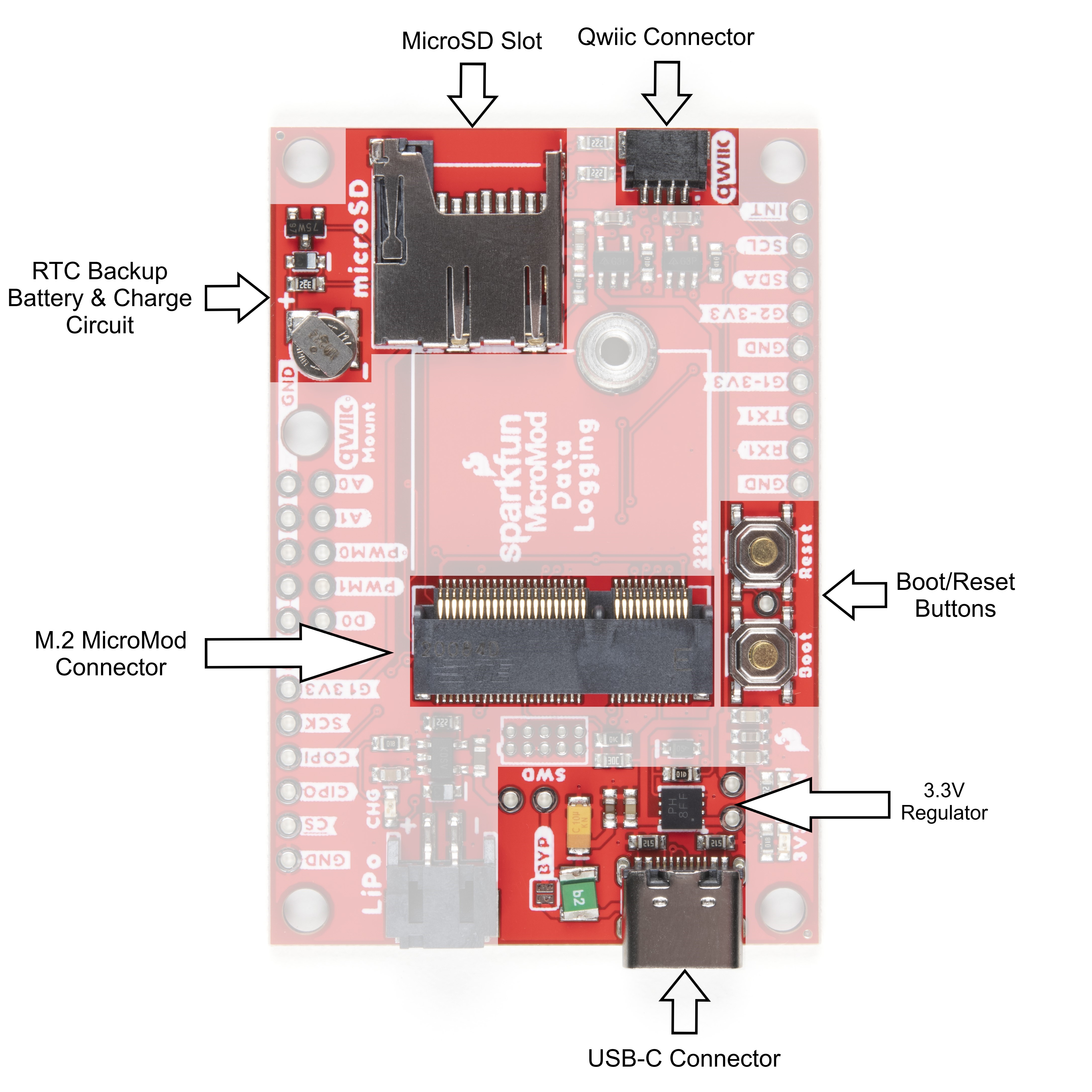
Common Components
Most SparkFun MicroMod Carrier Boards will have some common components and all MicroMod Carrier Boards
will have the keyed M.2 MicroMod Connector to plug your processor into. The photo and list below outline some of
the components included on most SparkFun MicroMod Carrier Boards.
M.2 MicroMod Connector - This special keyed M.2 connector lets you install your MicroMod Processor
Board of choice on your Carrier Board.
USB-C Connector - Connect to your computer to program your Processor Board and also can provide
power to your MicroMod system.
3.3V Regulator - Provides a regulated 3.3V and sources up to 1A.
Qwiic Connector - The standard Qwiic connector so you can add Qwiic devices to your MicroMod system.
Boot/Reset Buttons - Push buttons to enter boot mode on Processor Boards and to reset your MicroMod
circuit.
Serial Communication
Asynchronous serial communication concepts: packets,
signal levels, baud rates, UARTs and more!
Serial Peripheral Interface (SPI)
SPI is commonly used to connect microcontrollers to
peripherals such as sensors, shift registers, and SD
cards.
SD Cards and Writing Images
How to upload images to an SD card for Raspberry Pi,
PCDuino, or your favorite SBC.
Getting Started with MicroMod
Dive into the world of MicroMod - a compact interface
to connect a microcontroller to various peripherals via
the M.2 Connector!
New!

RTC Backup Battery & Charge Circuit - 1mAh backup battery for the RTC for certain MicroMod
Processor Boards . Receives charge voltage from 3.3V.
microSD Slot - Insert a µSD card formatted to FAT32(?) here to log your data.
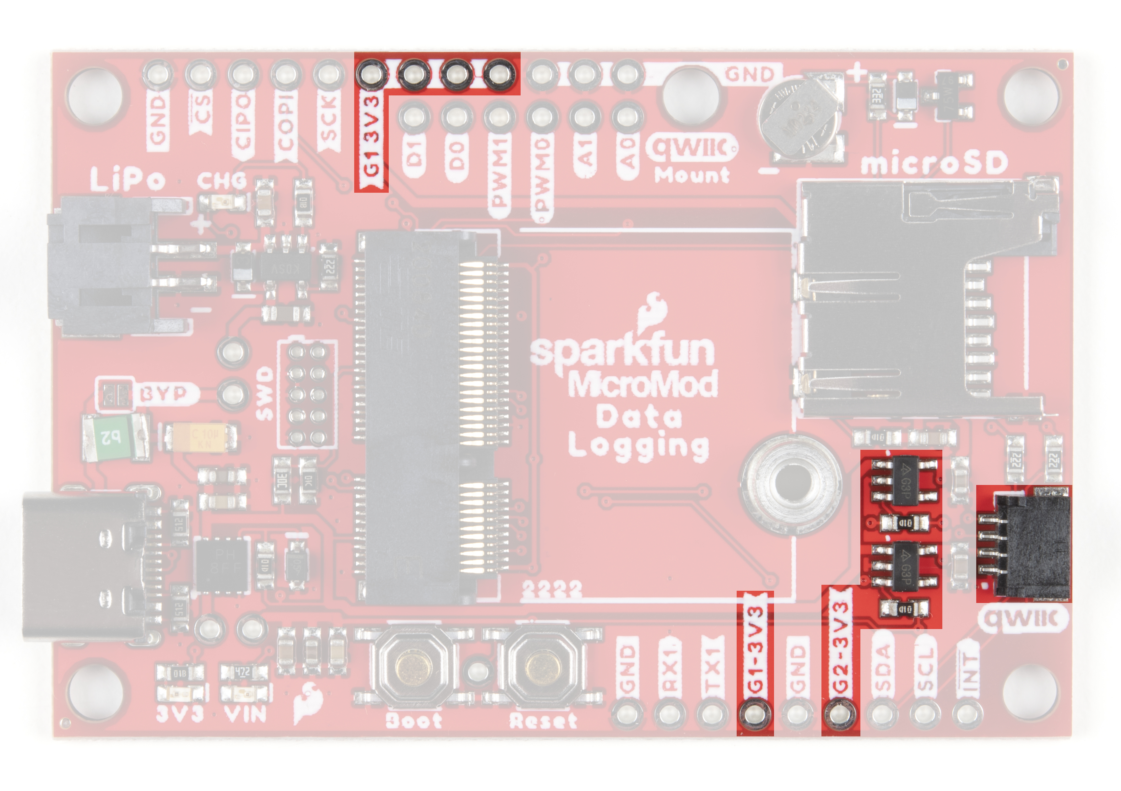
Power Control Circuit
The Data Logging Carrier Board features two 3.3V/600mA voltage regulators that have their Enable pins tied to
I/O pins on an attached MicroMod Processor Board. This allows control of the regulators' output with a few lines of
code making it extremely simple to control and conserve power in battery-powered applications. The G1-3V3 line
is controlled by G1 on the MicroMod Processor and the G2-3.3V circuit is (as you may suspect) is controlled by G2
on the MicroMod Processor. The G1-3.3V power circuit is tied to several pins highlighted in the below photo for
extra flexibility powering external devices. The G2-3V3 output is tied to the 3.3V pin on the Qwiic connector as well
as a dedicated PTH pin labeled G2-3V3.
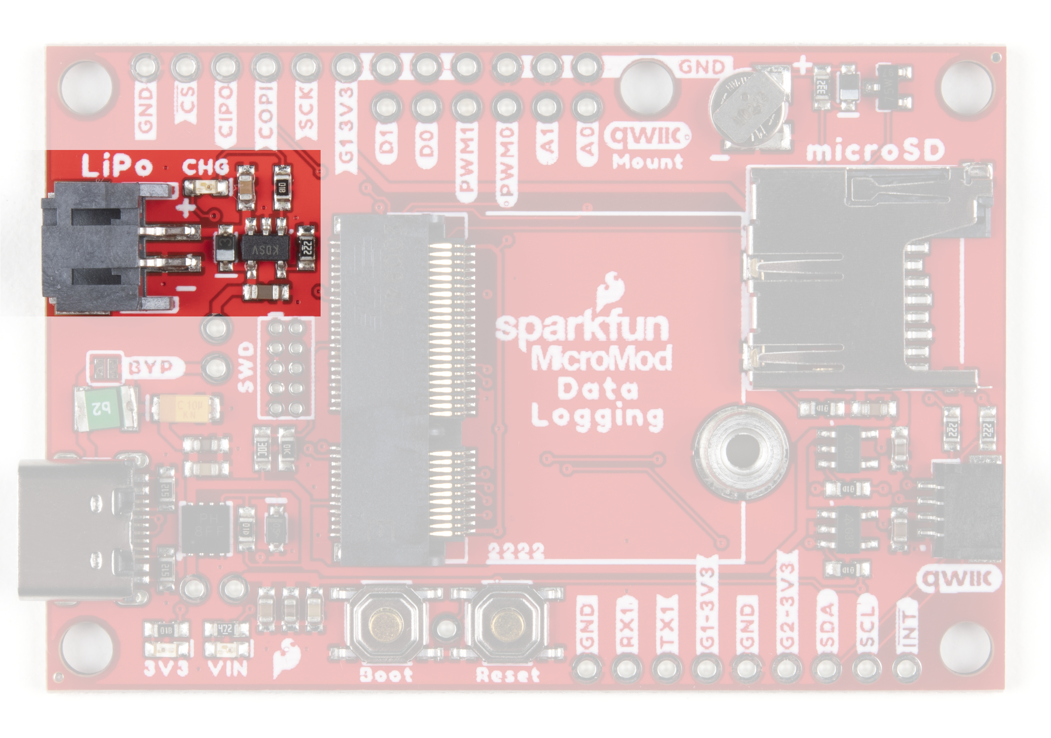
Battery Charging Circuit
The board also has a MCP73831 Single-Cell Lithium-Ion/Lithium-Polymer Charge IC so you can charge an
attached single-cell LiPo battery. The charge IC receives power primarily from USB and can source up to 450mA
to charge an attached battery.

Data Logging Connections
Along with the Qwiic connector mentioned in the Common Components, the Data Logging Carrier Board breaks
out several other pins to connect UART, SPI and other I/O devices. The primary SPI pins are netted to the µSD
slot and a PTH header near the LiPo battery connector. A second Chip Select pin tied to G0 is broken out to that
same header.
Note: µSD Chip Select is tied to the SPI_CS chip select pin on the M.2 Connector. Refer to your Processor
Board's documentation for information on how to properly define that pin in your code.
A UART PTH header connects to RX1 and TX1 for serial data logging and A0, A1, PWM0, PWM1, D0 and D1 are
routed to dedicated PTH pins as well. Lastly, if users prefer a soldered connection instead of Qwiic, the primary I C
bus is broken out to PTH pins.
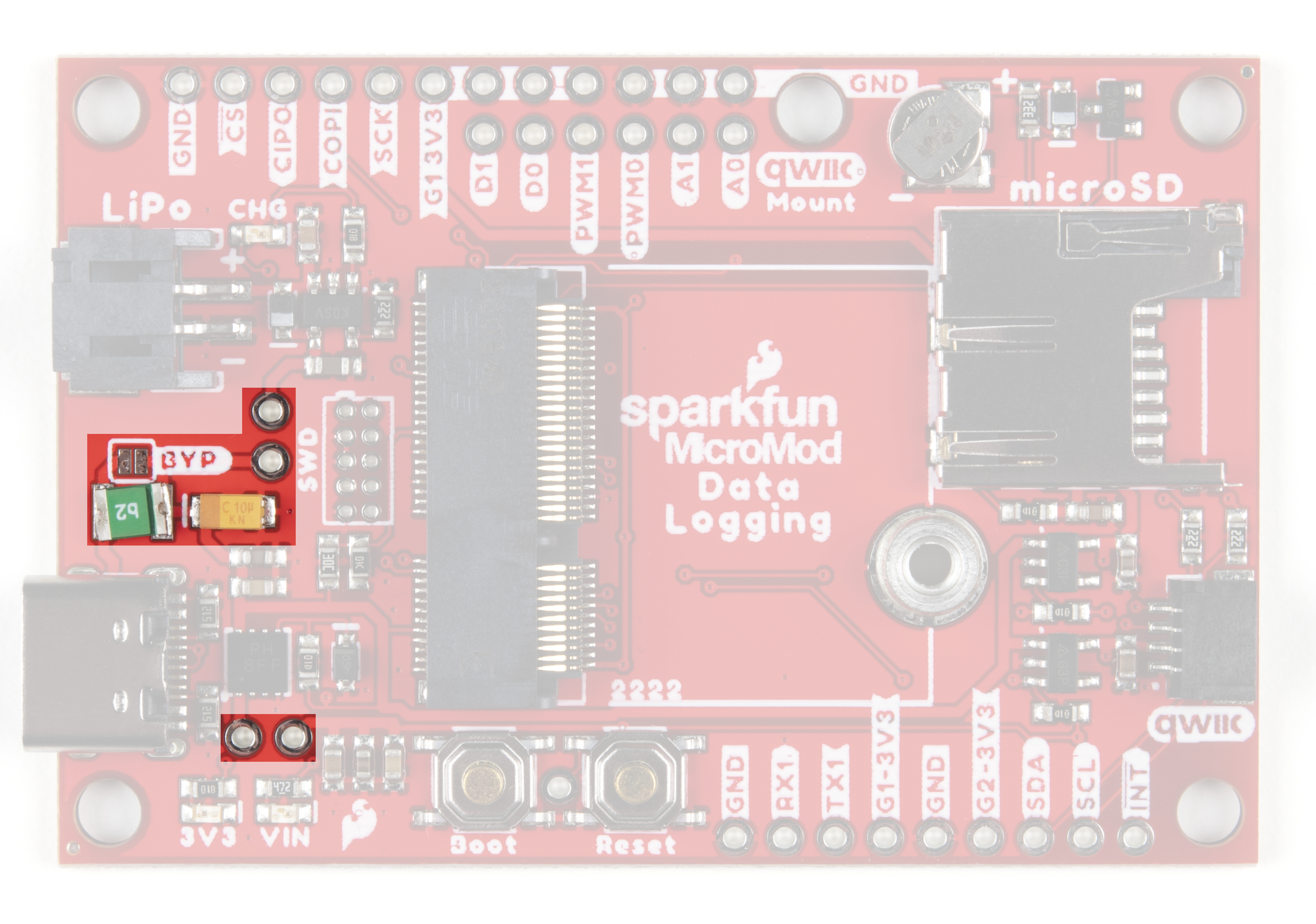
JTAG
An unpopulated JTAG footprint is available for more advanced users who need breakpoint level debugging. We
recommend checking out our JTAG section for the compatible male header and a compatible JTAG programmer
and debugger.
2

Solder Jumpers
If you have never worked with solder jumpers and PCB traces before or would like a quick refresher, check
out our How to Work with Solder Jumpers and PCB Traces tutorial for detailed instructions and tips.
There are seven solder jumpers on the Data Logging Carrier Board labeled I C, MEAS, BYP, VIN, 3V3, VE, and
BATT. In this section we'll detail the functionality and default states of each jumper.
Jumper
Name/Label
Description Default
State
I C Pull-Up /
I2C
Pulls the Qwiic SDA/SCL lines to 3.3V via two 2.2KΩ resistors CLOSED
Measure /
MEAS
Open this jumper to probe the current draw at the 3.3V output of the regulator. For
help measuring current, take a look at our How to Use a Multimeter tutorial.
CLOSED
Bypass /
BYP
The "penny-in-the-fuse" jumper. Bypasses the 6V/2A fuse and nets VIN and V_USB
together to allow >2A current flows. Close only if you know what you are doing!
OPEN
VIN /
VIN_LED
Connects the 5V/VIN LED to 3.7-6V (typ. 5V from USB) via a 4.1KΩ resistor. Open
to disable the VIN LED.
CLOSED
3V3 /
3V3_LED
Connects the 3.3V LED to 3.3V via a 1KΩ resistor. Open to disable the 3.3V LED. CLOSED
Voltage
Enable / VE
Close this jumper to enable processor control of the 3.3V bus. OPEN
Battery /
BATT
Open this jumper to measure current draw from the battery or to switch primary
power from USB to battery.
CLOSED
2
2

Having trouble viewing the detail in either photo? Click on them for a larger view!
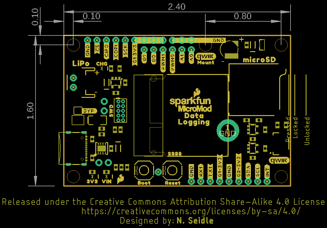
Board Dimensions
The MicroMod Data Logging Carrier Board measures 2.40" x 1.60" (60.96mm x 40.64mm) and has five mounting
holes that fit a 4-40 screw. Take note of the mounting hole labeled "Qwiic Mount" above the µSD slot as it can
work as single mount for a Qwiic breakout (or other sensor) or you can pair it with the outer mount in the "top-right"
corner for a more secure mounting option. We demonstrate using these two mounts for a Qwiic breakout in the
following section, Hardware Assembly.
Now that we're familiar with the hardware on the MicroMod Data Logging Carrier Board, it's time to plug your
Processor Board and peripheral sensors in and start logging some data. Next up we'll cover some assembly tips.
Hardware Assembly
Inserting the Processor Board
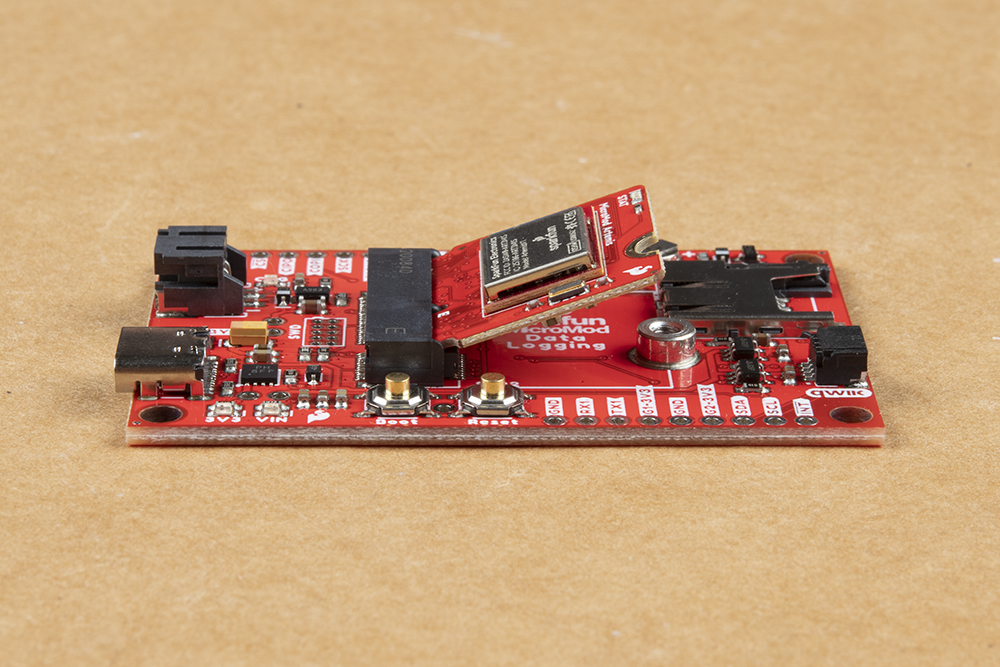
With the M.2 MicroMod connector, connecting your processor board is easy. Match up the key on your processor's
beveled edge connector to the key on the M.2 connector on your Carrier Board. At a 45° angle, insert the
processor board to the M.2 connector. The Processor Board will stick up at an angle as seen here:

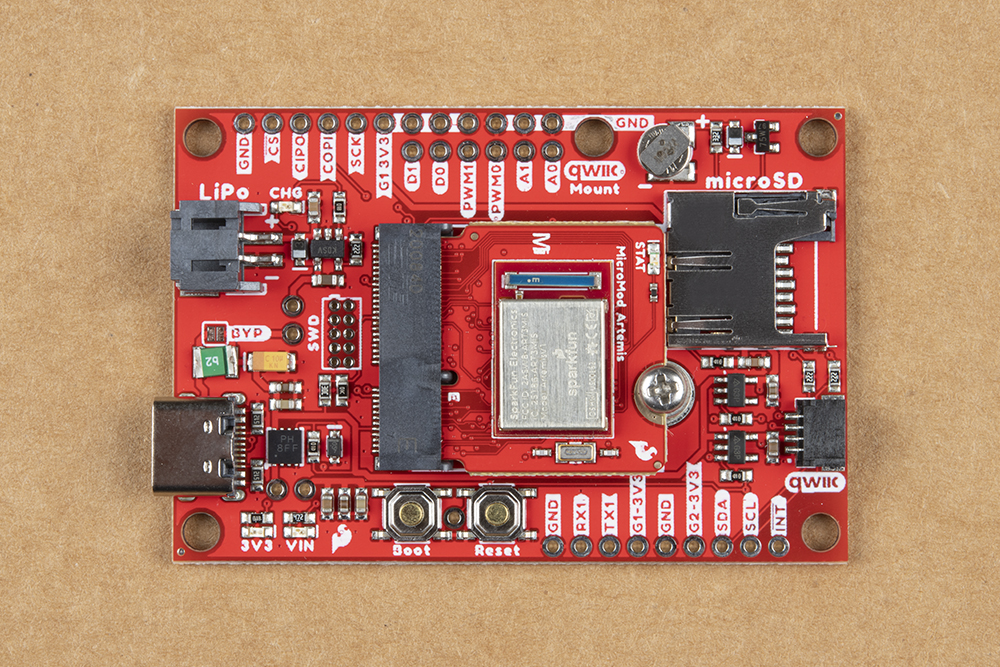
Once the board is in the socket, gently press the Processor Board down, grab the set screw and tighten it with a
Phillip's head screwdriver:
Once the Processor Board is secure, your assembled MicroMod system should look similar to the image below!
Note: There is technically no way to insert the processor backward since the key prevents it from mating with
the M.2 connector. As an extra safeguard to prevent inserting a processor improperly or with a poor
connection, the mounting screw will not match up if the Processor Board is not plugged in entirely.
Data Logging Peripherals
As we mentioned previously, the Data Logging Carrier Board offers several ways to connect your sensors or other
peripherals you intend to log data from.
If you are using a Qwiic breakout just connect it using a Qwiic cable to the Qwiic connector on the Carrier Board. If
your I C device is not Qwiic-enabled, you can either use a Qwiic adapter cable or connect the peripheral to the
Carrier Board using the 0.1"-spaced PTH pins for I C. Soldering is strongly recommended for this approach but if
you just want a temporary connection for prototyping you can use IC Hooks like these or these.
2
2

For alternate data inputs using SPI, Serial UART or other inputs (analog, digital, etc.), you will need to connect
them to the 0.1"-spaced PTH pins broken out on either side of the Data Logging Carrier Board using one of the
methods covered above. Take note of which 3.3V rail you are connecting them to for easy reference when
controlling power to your devices after everything is soldered together.
Before powering everything up, insert your microSD card into the card slot and press it in to lock it into place.
Connecting Everything Up
With your processor inserted and secured it's time to connect your MicroMod Data Logging Carrier Board to your
computer using the USB-C connector. Depending on which Processor Board you choose and which drivers you
already have installed, you may need to install drivers for your processor board. Refer to your Processor Board's
Hookup Guide for detailed instructions on how to install them. At this point you can also connect your battery for
charging or to power the circuit once USB power is removed.
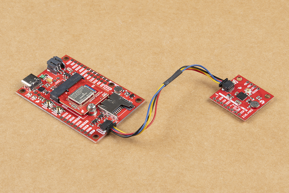
This demo circuit uses the SparkFun GPS Breakout - ZOE-M8Q (Qwiic) and GPS/GNSS Magnetic Mount
Antenna.
Note: Make sure that for whichever processor board you choose, you have the correct board definitions
installed.
For this particular tutorial, we are using the Artemis MicroMod Processor Board. Board definitions for this
processor board can be found in the Software Setup and Programming section of the Artemis MicroMod
Processor Board Hookup Guide.
If you are using a different processor board, go to our MicroMod Processor Boards landing page, find your
processor board, and head on over to that tutorial for help installing your board definition.
Table des matières
Autres manuels sparkfun Conseil des transporteurs


Manuels Conseil des transporteurs populaires d'autres marques

CTJ
CTJ TX2 Manuel utilisateur

Amfeltec
Amfeltec AngelShark Series Manuel utilisateur

Advantech
Advantech CPC-2420 Manuel d'installation et d'exploitation

Bob's Space Racers
Bob's Space Racers BSR-3000 Manuel utilisateur

RTimes
RTimes Z509 Manuel utilisateur

mikroElektronika
mikroElektronika Clicker 2 Manuel utilisateur


