Sofraser 9100 Manuel utilisateur

Original version
REF.: 423-0
9100
Viscosity and temperature
transmitter
Tec nical Manual


Tec nical Manual 9100
REF: 423/0 3
IMPORTANT
THE OFFSET ADJUSTMENT IN THE AIR
MUST BE THE FIRST TASK COMPLETED.
Offset adjustment procedure is detailed in § 3.3.
1. CLEAN AND DRY THE SENSOR ROD.
2. BE SURE THE PROCESS IS EMPTY. THE ROD MUST BE VIBRATING IN THE AIR.
3. INSTALL THE SENSOR ON THE PROCESS AND FIX IT WITH ITS 4 SCREWS.
4. POWER ON THE DEVICE, WAIT AT LEAST 30 MINUTES.
5. PRESS THE “HOME” BUTTON UNTIL REACHING THE OFFSET MENU AND PRESS “OK”.
6. FOLLOW THE INSTRUCTIONS DISPLAYED ON THE ELECTRONICS SCREEN.
7. PRESS “OK” TO ADJUST THE OFFSET. IT MEANS THE RAW SIGNAL IS SHIFTED TO THE
VOLTAGE REFERENCE DEFINED IN THE FACTORY CALIBRATION STAGE.
THE NEW OFFSET VALUE IS THEN DISPLAYED.

Tec nical Manual 9100
REF: 423/0 4
Table of co te ts
1.
TRANSMITTER PRINCIPLE ................................................................................................................. 5
2.
TRANSMITTER TECHNICAL CHARACTERISTICS ............................................................................. 6
2.1
Electronic device size ............................................................................................................................................ 6
2.2
Main features .............................................................................................................................................................. 7
2.2.1
Best performance conditions .................................................................................................. 7
2.2.2
Display ..................................................................................................................................................... 7
2.3
Connections ................................................................................................................................................................ 7
2.3.1
Top connector – current outputs .......................................................................................... 8
2.3.2
Top connector – Power supply and RS485 port .......................................................... 8
2.3.3
Bottom connector – sensor’s coils ........................................................................................ 9
2.3.4
Bottom connector – Pt100 temperature probe & eart ......................................... 9
2.4
Backlig t setting .................................................................................................................................................... 10
3.
THE 9100 OPERATING FUNCTIONS ................................................................................................. 11
3.1
Start and menus ....................................................................................................................................................... 11
3.2
Raw data ....................................................................................................................................................................... 12
3.3
Offset ............................................................................................................................................................................... 12
3.4
Viscosity and temperature units .................................................................................................................. 13
3.5
C eck 4-20 mA ........................................................................................................................................................ 14
3.6
Correlation .................................................................................................................................................................. 14
3.7
Enable or disable temperature ...................................................................................................................... 15
4.
RS485 FRAME PROTOCOL ............................................................................................................... 16
5.
SOFRASER INTERFACE SOFTWARE ................................................................................................ 18
5.1
T e main features ................................................................................................................................................... 18
5.2
T e user-friendly interface ................................................................................................................................ 18
6.
TROUBLESHOOTING ..........................................................................................................................19

Tec nical Manual 9100
REF: 423/0 5
1. Tra smitter pri ciple
T e measuring c ain is composed of t ree inseparable elements: t e sensor, its cable and t e 9100
transducer t at controls it. T e sensor cannot be used wit anot er transducer or anot er
cable type or lengt because t ey are all a part of t e resonant loop so t ey are matc ed
toget er as one vibrating system.
T e active part of t e sensor is composed of a vibrating rod eld in oscillation at resonance frequency
by driving magnets. W en t e rod is immersed into a viscous material, t e amplitude of t e
vibration is dampened. T e vibration amplitude varies according to t e product viscosity
w ere t e rod is immersed.
T e sensor receiving coil detects t e response and t e signal is converted to a viscosity value
t roug t e electronic device. T e factory calibration is performed wit standard oils.
T e transducer acquires t e coils’ amplitudes and frequency and generates various signals. T ese
signals represent t e properties being measured. It is also in c arge of powering t e w ole
system. It gives viscosity and temperature information t roug t e serial communication and
displays it. T e transmitter also allows simple settings as t e very important “zero in t e air”
procedure.

Tec nical Manual 9100
REF: 423/0 6
2. Tra smitter tech ical characteristics
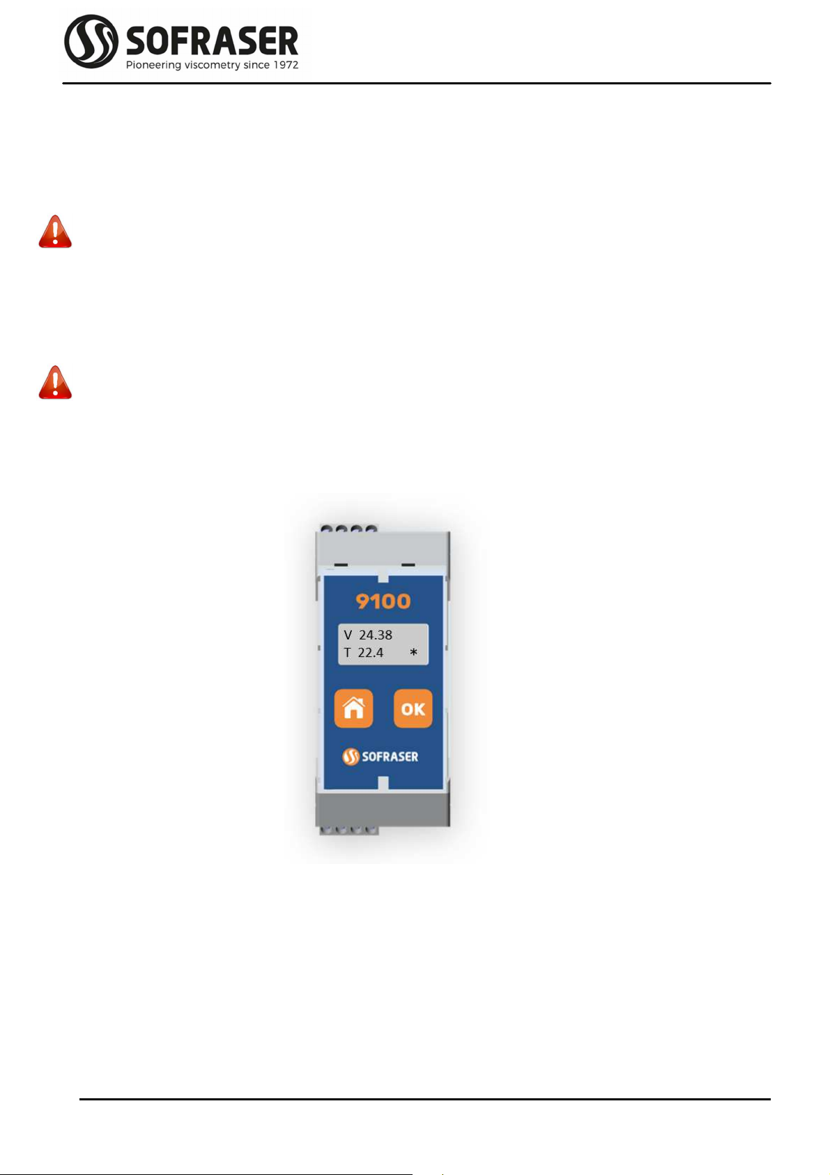
2.1 Electronic device size
T e electronic box as t e purpose to be fixed on a DIN rail, close to t e process line. Its LCD screen
continuously displays t e viscosity value and, w en connected to a Pt100 probe, t e
temperature value.
T e ID label is stuck on a side of t e box. Main information is written down. T ere are also ot er
stickers on eac connector to remind ow to connect t e sensor, t e outputs and t e power
supply (see §2.3).
It as an IP20 rating. Its weig t is about 200 g. Hereunder are t e different views and t e associated
dimensions (in mm) of t e device.
45 mm
105 mm
Top connectors
Bottom connectors
Bottom connectors
Side view
113 mm
Tec nical Manual 9100
REF: 423/0 7
2.2 Main features
2.2.1
Best performance conditions
T e processor must be connected to a 24 VDC (± 2.4 V) stabilized and filtered power supply.
It is very important to respect t e polarity.
T e operating temperature for t is transmitter is up to 50 °C.
It is recommended to install t is transmitter in a safe place wit a stable temperature and non-
condensing atmosp ere.
To ensure t e proper be avior of t e two 4-20 mA current outputs, it is ig ly recommended to
connect t em to a PLC or a regulator t roug a galvanic isolated device (one for eac current
output).
Never connect t e 4/20 mA outputs to a power supply, an active PLC input or tester
2.2.2
Display
T e 9100 transmitter device as a 2-line alp anumeric backlig ting LCD screen. T e effective
dimensions of t is screen are 40 mm * 10 mm. One line can display 8 digits. T is screen is
s owing t e different menus wit t e elp of t e 2-button face plate.
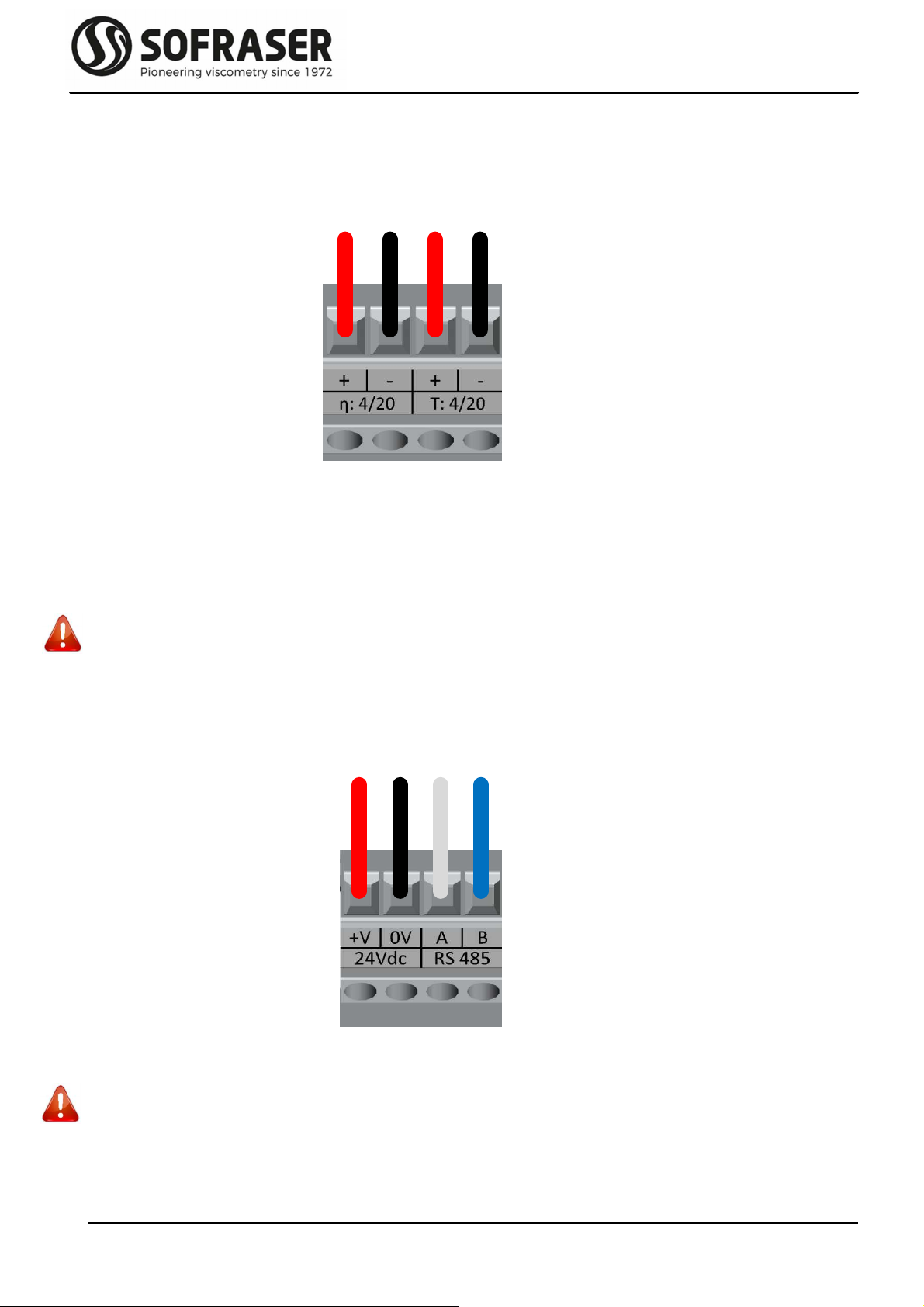
2.3 Connections
All t e connections to t e electronic device are made t roug four connectors.
T ere are two 4-pin connectors on t e top for t e power supply and outputs and two ot er 4-pin
connectors on t e bottom for t e sensor. Refer to t e sensor’s tec nical manual for wires A to
F identification. Connections ave to be made by t e user scrupulously respecting t e
following indications.
Tec nical Manual 9100
REF: 423/0 8
Power supply 24 V 0 V A B RS485 bus
2.3.1
Top connector – current outputs
If t e current outputs are used, t e plugging sc eme of t e connector is as follows:
T e Pins η: 4/20 and T: 4/20 are used to connect t e 4/20 mA outputs for Viscosity and Temperature.
T ey ave been calibrated according to customer's request. T ey must be connected to
installations wit an impedance of not more t an 400Ω. It is recommended to use s ielded
cables for t ese outputs and t e s ield s ould be connected to t e eart . T ey are already
powered internally.
W en t e measured value is out of t e configured range of t e 4/20 output (below minimum value
or over maximum value), t e output passes in default mode and is forced to 2 mA.
Never connect t e 4/20 mA outputs to a power supply, an active PLC input or tester
2.3.2
Top connector – Power supply and RS485 port
T e plugging sc eme of t e connector is as follows:
Pins 24Vdc +V and 0V are for t e 24 VDC (± 2.4 V) stabilized and filtered power supply.
Caution: watc out t e polarity
Pins A and B are used to connect t e RS-485 cable in order to communicate wit an external
console.
Visc 4/20 mA Temp 4/20 mA
Tec nical Manual 9100
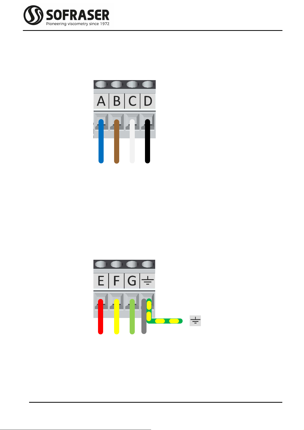
REF: 423/0 9
E F G met l
A B C D
2.3.3
Bottom connector – sensor’s coils
T e plugging sc eme of t e connector is as follows:
Pins A, B, C and D make t e connection between t e electronic board and t e coils wires of t e MIVI
sensor cable. T is is ow t e driving signal is generated and ow t e receiving signal is
measured.
2.3.4
Bottom connector – Pt100 temperature probe & eart
T e plugging sc eme of t e connector is as follows:
Pins E, F and G are used to connect t e 3 wires of t e optional Pt100 temperature probe.
Last Pin must be connected to
- t e “metal” wire of t e MIVI sensor cable
- t e ground eart of t e works op
Tec nical Manual 9100
REF: 423/0 10
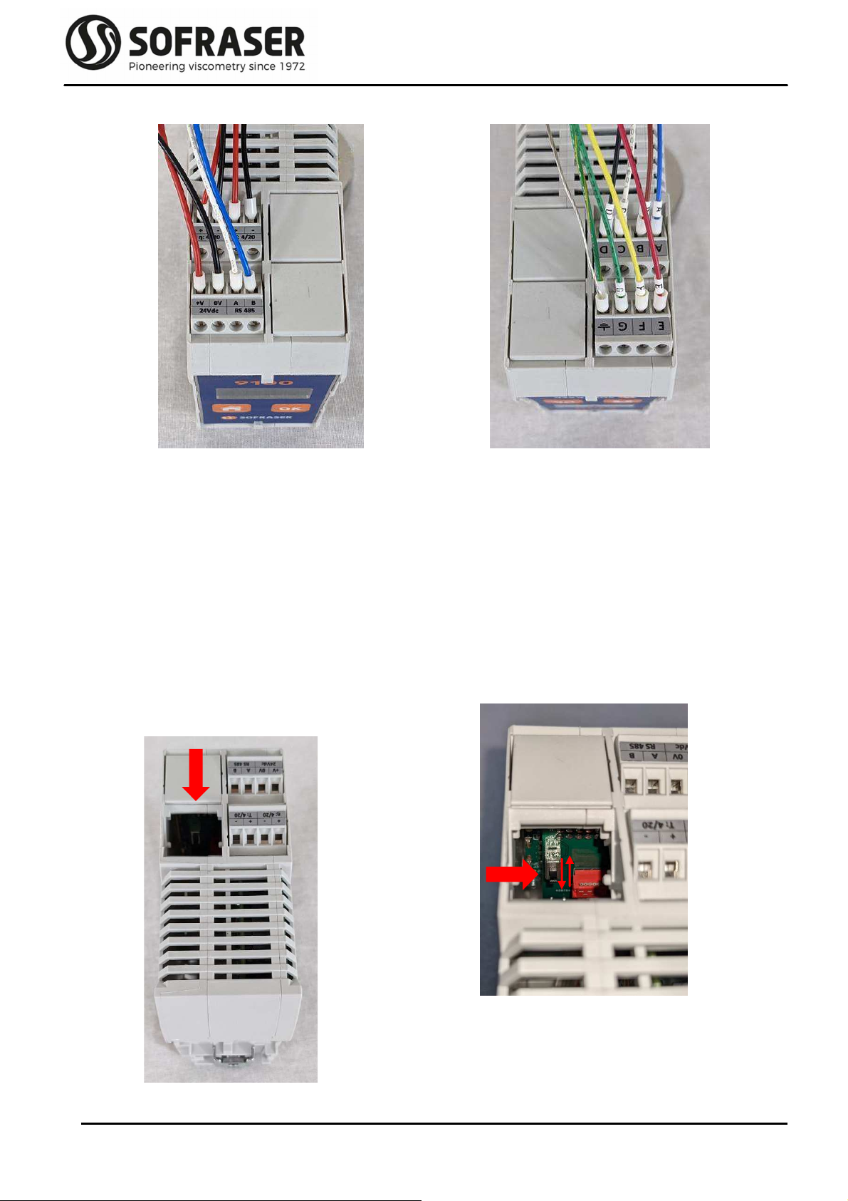
2.4 Backlig t setting
In standard, 9100 is delivered wit disabled display backlig t. T e backlig t can be enabled t anks
to a switc located on t e back side of t e display. Hereunder t e procedure t at describes ow to
access to t e switc and ow to set it.
Power off t e transmitter and remove t e cover
on t e top side of t e transmitter wit a small
flat ead screw driver.
C ange t e position of t e switc to active
and deactivate t e backlig t.
Put t e cover back on.
Top connectors
Current outputs
24VDC power supply & RS485 output
Bottom connectors
Viscosity sensor
Eart & Pt100 temperature probe
Table des matières
Autres manuels Sofraser Émetteur

Manuels Émetteur populaires d'autres marques


Dejero
Dejero EnGo 3x Manuel utilisateur

Rosemount
Rosemount 4600 Manuel utilisateur

Speaka Professional
Speaka Professional 2342740 Manuel utilisateur

trubomat
trubomat GAB 1000 Manuel utilisateur

Teledyne Analytical Instruments
Teledyne Analytical Instruments LXT-380 Manuel utilisateur

Rondish
Rondish UT-11 Manuel utilisateur


