SMARTfit PowerForce Manuel utilisateur

PowerForce –User Manual
Radlabor GmbH | Heinrich-von-Stephan-Str. 5c | 79100 Freiburg | Germany
www.smartfit.bike | www.radlabor.de
PowerForce
System
User manual
-
wireless edition

PowerForce –User Manual
Radlabor GmbH | Heinrich-von-Stephan-Str. 5c | 79100 Freiburg | Germany
www.smartfit.bike | www.radlabor.de
Inhalt
Important warnings................................................................................................................................... 3
1. Introduction ........................................................................................................................................... 4
1.1 Pedal forces .................................................................................................................................... 4
1.2 Force components.......................................................................................................................... 5
Fr (resultant / total –force).............................................................................................................. 5
Fe (effective / tangential –force) .................................................................................................... 5
Fu (unused / radial –force).............................................................................................................. 5
1.3 Measuring Principle ........................................................................................................................ 6
1.4 Technical Data –Wireless edition ................................................................................................. 7
2. After unpacking..................................................................................................................................... 8
2.1 components .................................................................................................................................... 8
2.2 Mounting.......................................................................................................................................... 9
3. Software Installation........................................................................................................................... 12
3.1 Install NI-DAQmx Driver................................................................................................................ 12
3.2 Install NI LabVIEW 2009 Runtime Engine Library....................................................................... 12
3.3 Install IMAGO Records®............................................................................................................... 12
4. IMAGO Record®.................................................................................................................................. 13
4.1 Introduction ................................................................................................................................... 13
4.2 First start and setup...................................................................................................................... 13
4.2.1 Load Setup-files ..................................................................................................................... 14
4.2.2 Set, save and load calibration values ................................................................................... 15
4.3 Description of IMAGO®................................................................................................................ 17
4.3.1 Main Menu.............................................................................................................................. 17
4.3.2 Index Tab ................................................................................................................................ 18
4.4 Measurement ................................................................................................................................ 21
5. CyclePlotAssistent.............................................................................................................................. 22
5.1 Quick buttons and contents ......................................................................................................... 24
5.2 Charts and Design......................................................................................................................... 25
5.3 Graph Selection............................................................................................................................. 26
5.4 Caption and legend....................................................................................................................... 27
5.5 Save quick button.......................................................................................................................... 28

PowerForce –User Manual
Radlabor GmbH | Heinrich-von-Stephan-Str. 5c | 79100 Freiburg | Germany
www.smartfit.bike | www.radlabor.de
Important warnings
Please read the following warnings, before beginning to use your PowerForce System. Otherwise,
your PowerForce could be damaged, or not function properly.
✓Do not over tight the pedals in the PowerForce System. Give some grease to the
connective sites to improve the reassembling of the pedals.
✓If your open a sensor, the transmitter unit or the connection box, the warranty is no
longer valid.
✓Never clean the sensor or the transmitter unit with water or use it in wet conditions.
✓Do not cramp the position switch –it is sensitive for pressure.
✓Check before each ride, that the sensors and the pedals are fixed properly.
✓When unplugging any connection, always pull straight down rather than sideways,
or you could damage connector pins. Never pull on the cable itself, but rather the
plug.
✓Carefully read through the full installation instructions before beginning, as
mounting the PowerForce System incorrectly can cause a fall or damage the
system.
✓Do not load the sensor with loads higher than 300kg.
PowerForce –User Manual
Radlabor GmbH | Heinrich-von-Stephan-Str. 5c | 79100 Freiburg | Germany
www.smartfit.bike | www.radlabor.de
1. Introduction
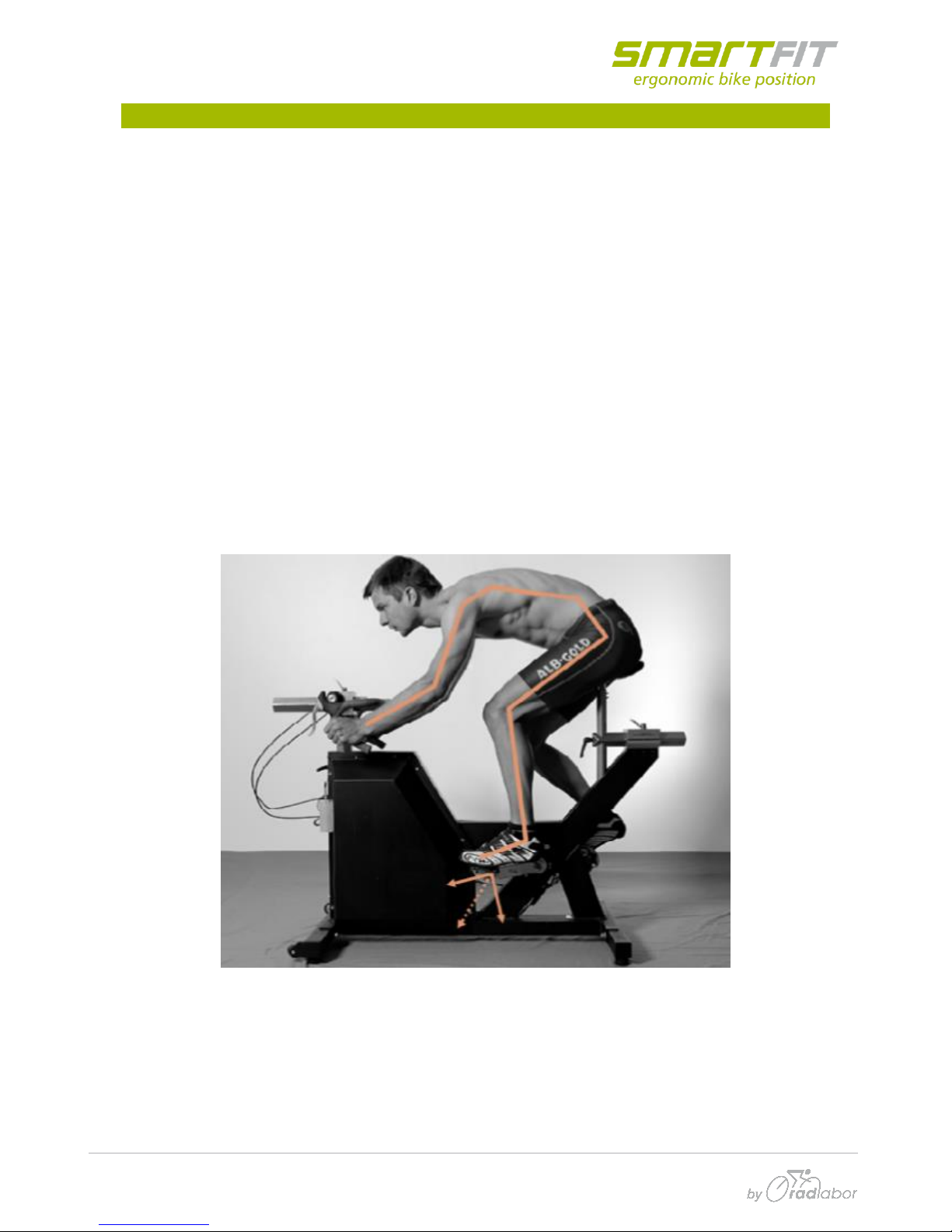
1.1 Pedal forces
In cycling the transfer of metabolic energy into physical power or velocity of the rider-bike-system is
not one-to-one. Environmental as well as mechanical and biomechanical factors affect cycling
performance. The propulsion of the bike is generated by pedal forces. Therefore, the determination
of pedal forces is a major prerequisite to analyze cycling performance capability from a
biomechanical point of view.
The question is not why to measure pedal forces but how to do it. Comparing other existing
instruments whose purpose is the determination of divers mechanical parameters concerning
cycling propulsion, there are some methodological or practical limitations regarding the
requirements of either a biomechanical lab or a sports related center.
The most important advantage of the PowerForce System is the fact that there is no restriction to a
certain pedal system. Cyclists do not have to change their pedal-shoe interface (cleats) if they want
to measure their pedal forces with the PowerForce.
PowerForce –User Manual
Radlabor GmbH | Heinrich-von-Stephan-Str. 5c | 79100 Freiburg | Germany
www.smartfit.bike | www.radlabor.de
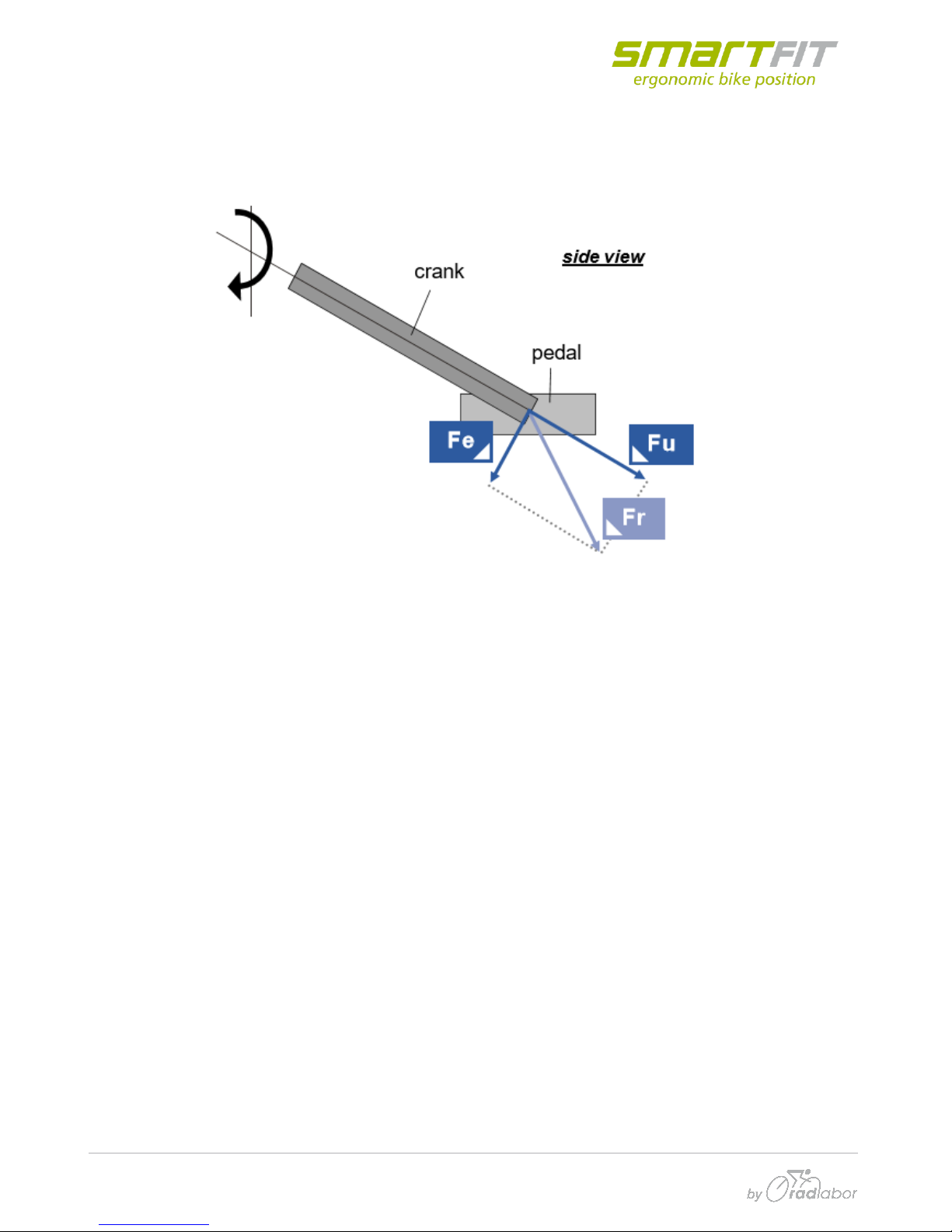
1.2 Force components
The PowerForce records the forces, which are performed on the pedal axis, separately for each leg.
Three force components (Fe, Fu und Fr) have to be differentiated.
Fr (resultant / total –force)
This is the total force which is generated by the athlete on the pedal. It is the vectorially sum of Fe
and Fu an is calculated, not measured.
Fr tells us about the total load, the rider applies to the system –the bike as well as to his own body.
Joint moments and forces result from (or cause) this component. Thus, e.g. inverse dynamics are
based on Fr.
Fe (effective / tangential –force)
Fe is the component of Fr which lies in moving direction of the crank/pedal which is a circle.
Therefore, the vector of Fe is always tangential to this circle or perpendicular to the crank. Fe is
responsible for the propulsion, but only if it is aligned forward with the rotating direction. If it is
aligned backward, e.g. if a rider does not pull up the pedal in the upstroke phase, Fe of the one side
must be subtracted from the other side.
Fu (unused / radial –force)
Fu is the component of Fr which does not generate any propulsion. It results in very small
deformation of the crank and pedal-axis. The direction off this force component is lengthwise to the
crank. The highest values appear around the bottom dead center (180° crank angle) where the
weight component (induces by the mass of the leg) adds to the muscular component.

PowerForce –User Manual
Radlabor GmbH | Heinrich-von-Stephan-Str. 5c | 79100 Freiburg | Germany
www.smartfit.bike | www.radlabor.de
1.3 Measuring Principle
The pedal force measuring device is built as an own mechanical construction which is mounted
between the crank and the pedal with an 12° forward rotation about the crank.
The system determines the magnetic field variations (Hall-Effect) because of the angular
displacement (~ 1/1000mm) of a small magnet in respect to a sensor.
Due to the specific circular construction of the force transmitting elements the applied force can be
divided into a radial and a tangential part. Positive tangential force (FT = Fe) is in the pedaling
direction and positive radial force (FR = Fu) is in the centrifugal direction. This principle allows every
pedal system to be screwed on.
12°
new (virtuell)
crank arm
pedal

PowerForce –User Manual
Radlabor GmbH | Heinrich-von-Stephan-Str. 5c | 79100 Freiburg | Germany
www.smartfit.bike | www.radlabor.de
1.4 Technical Data –Wireless edition
Mass of single sensor including radio: 370 g
Mass of receiver: 116 g
Measurement range: -500 up to 1500 N
Breaking load: ~3000 N
Sampling frequency pedal force: ~500 Hz
Wireless band: ISM Band: 2,4 GHz
Transmission distance:
Indoor: 3 –5 m
Outdoor: 2 –3 m
Battery Type: NiCd
800 mAh
Time for continual use: 6 –8 h
Resolution: 12 Bit
PowerForce –User Manual
Radlabor GmbH | Heinrich-von-Stephan-Str. 5c | 79100 Freiburg | Germany
www.smartfit.bike | www.radlabor.de
2. After unpacking
✓First read and follow these instructions!
✓Unpack all materials very carefully!
✓The PowerForce System is high sensitive electronic. So, handle all parts with highest
care
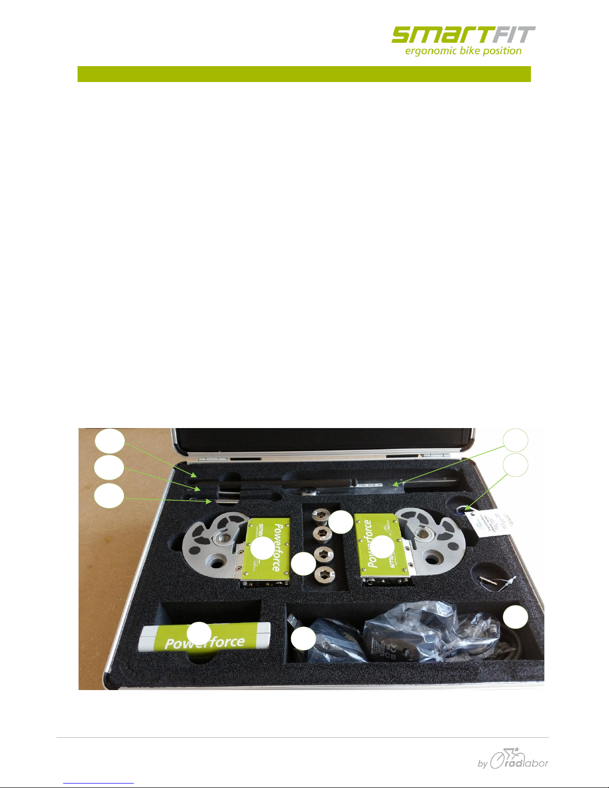
2.1 components
Check the content inside the suitcase
[1] 2x PowerForce sensor (left & right), with mounted transmitter (Accumulator included,
two protector caps mounted)
[2] 1x Base station (receiver)
[3] 1x Adjustment Tool
[4] 2x adjustment tools screws
[5] 2x crank –sensor screws
[6] 2x Accumulator Charger
[7] 1x Serial USB cable (Base station to PC)
[8] 1x USB License Dongle
[9] 1x 10mm Allen Key
[10] 1x 2,5mm Allen Key
[11] 1x 10mm Wrench
[12] 1x Calibration printout
2
1
1
8
7
3
4
5
6
9
10
11
PowerForce –User Manual
Radlabor GmbH | Heinrich-von-Stephan-Str. 5c | 79100 Freiburg | Germany
www.smartfit.bike | www.radlabor.de
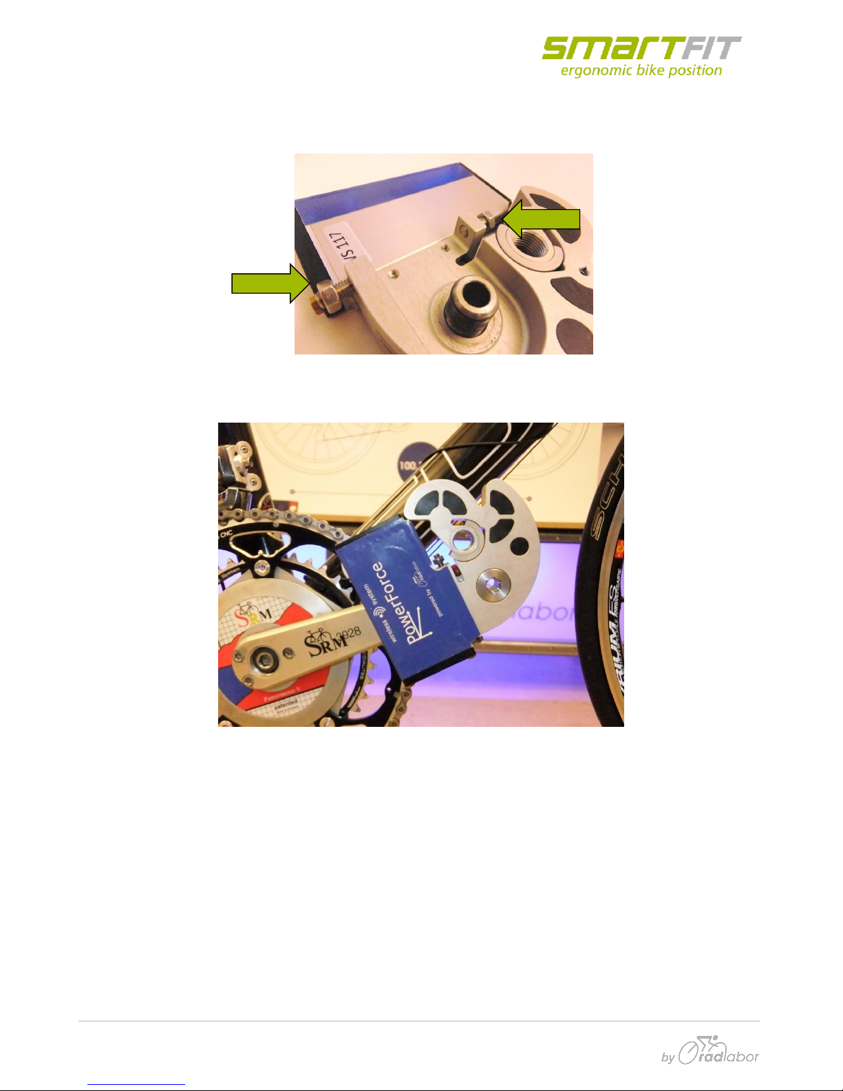
2.2 Mounting
To improve the measurement, it is important to fix the sensor in appropriate position on the ankle.
Before the mounting, make sure, that the adjustment screws are screwed out:
so, that the sensor has some space to move. Then mount the sensor on the crank:
PowerForce –User Manual
Radlabor GmbH | Heinrich-von-Stephan-Str. 5c | 79100 Freiburg | Germany
www.smartfit.bike | www.radlabor.de
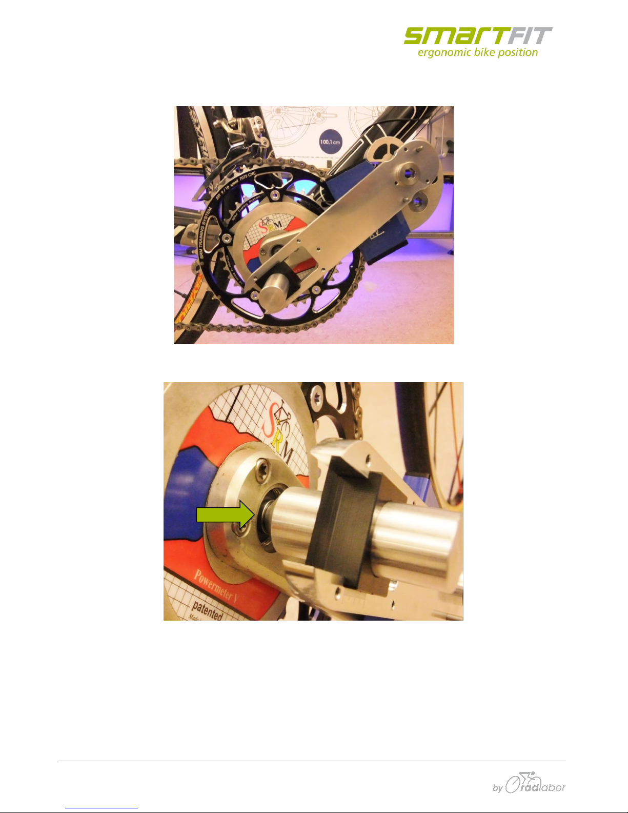
Adjust the apex on the cone-bolt. Put the little bolts in the middle and fix the adjustment tool (hand-
tight) onto sensor, by using the corresponding screw for each site:
Put the cone of the adjustment tool into the center of the bottom bracket screw:
Table des matières
Autres manuels SMARTfit Équipement de fitness


