Smacq Technologies USB-5200 Series Manuel utilisateur

USB-5200 Series Multifunctional
Data Acquisition Devices
User Manual
Rev. C
Beijing Smacq Technology Co., Ltd.
Smacq.com
Smacq.cn
竺
macq.
Smacq

Statement
Copyright
©2018 Beijing Smacq Technology Co., Ltd. All rights reserved
No content of this manual may be reproduced, modified or abridged without prior
consent and written permission.
Trademark information
Smacq is a registered trademark of Beijing Smacq Technology Co., Ltd The
names of the other products and companies mentioned in this document are
trademarks or trade names of their respective companies.
Other Disclaimer
1 |
Contact Us
If you have any questions or need assistance in using this product or this
document, please contact us via:
Phone:(+86)10-52482802
E-Mail: [email protected]
Website: http://www.smacq.com
http://www.smacq.cn
The information provided in this document may be modified and updated in
subsequent versions without prior notice.
Smacq does not provide any warranties, express or implied, for this document
as well as the information inside it, including but not limited to implied
warranties of the marketable nature of the product and its suitability for a
particular purpose.
There may be a chance that inaccurate descriptions or errors exist in this
document. Smacq does not hold any liability for accidents because of the
information and deductive functions provided in this manual, as well as the
resulting loss of any chance because of the use of this document.
Smacq reserves the rights to change product specifications, prices, and decide
whether to stop the production.

2 |
Safety Requirements
Warning
Warning
Warning
Warning
Warning
Warning
Only the voltage within the specified range can be connected.
Voltage exceeding the specified range may cause damage to the
device, and even present a negative impact on personal safety.
Check the product specification for detailed reference to the range
of voltages that can be connected by each port.
Do not attempt to operate the device in other ways that are not
mentioned in this document. Incorrect use of the device may be
dangerous. In the event of device damage, the internal security
protection mechanism will also be affected.
Do not attempt to replace device components or change devices
in other ways that are not mentioned in this document. Do not
repair the device yourself in the event of a product failure.
Do not use the device in an environment where an explosion may
occur or where flammable flue or gas is present. If you must use
the device in this kind of environment, please fit it into a proper
case.
While the device is running, all chassis covers and fill panels need
to be closed.
For equipment with exhaust vents, do not insert foreign objects
into the vents or block air circulation in the vents.
3 |
Measurement Categories
Warning For use in measurement category I (CAT I) only. Do not use in
measurement category II/III/IV. Use this device to connect
signals or make measurements.
Measurement categories Note
Measurement categories I (CAT I) means that measurements are made on a circuit that
is not directly connected to the main power supply. For example, a circuit that is not
exported from the main power supply, especially a circuit that is exported from a
protected (internal) primary power supply, is measured. In the latter case, the
instantaneous stress will change. Therefore, the user should be aware of the
instantaneous affordability of the device.
Measurement categories II (CAT II) means that measurements are made on a circuit
that is directly connected to a low-voltage device. For example, a measurement on
household appliances, portable tools and similar equipment.
Measurement categories III (CAT III) means that measurements are made in
construction equipment. For example, a measurement on the distribution boards, circuit
breakers, wiring (including cables, Busbars, junction boxes, switches, sockets) in fixed
equipment and equipment for industrial use and certain other equipment (for example,
fixed motors that are permanently connected to fixtures).
Measurement categories IV (CAT IV) means that measurements are made on the source
of low-voltage equipment. For example, a measurement on a meter, a major overcurrent
protection device, and a pulse control unit.
Environment
Temperature
Operating 0℃~ 55℃
Storage -40℃~ 85℃
Humidity
Operating 5%RH ~ 95%RH, no condensation
Storage 5%RH ~ 95%RH, no condensation
Pollution degree 2
Highest elevation 2000 m

4 |
Some of the substances contained in this product may be harmful
to the environment or human health. In order to avoid releasing
harmful substances into the environment or endangering human
health, it is recommended that appropriate methods be used to
recover this product to ensure that most materials can be properly
reused or recycled. For information about processing or recycling,
please contact your local professional organizations.
Pollution degree description
Pollution degree 1: No pollution, or only dry non-conductive pollution. This pollution
degree has no effect. For example: a clean room or an air-conditioned office
environment.
Pollution degree 2: Generally only dry non-conductive pollution occurs. Temporary
conduction can sometimes occur due to condensation. For example: General indoor
environment.
Pollution degree 3: Conductive pollution occurs, or dry non-conductive pollution becomes
conductive due to condensation. For example, an outdoor sheltered environment.
Pollution degree 4: Permanent conductive pollution caused by conductive dust, rain, or
snow. For example: Outdoor places.
Recycle precautions
Warning

5 |
CONTENT
STATEMENT.............................................................................................................. 1
SAFETY REQUIREMENTS........................................................................................... 2
MEASUREMENT CATEGORIES................................................................................... 3
ENVIRONMENT......................................................................................................... 3
1. GETTING STARTED............................................................................................. 7
1.1. PRODUCT INTRODUCTION..................................................................................7
1.2. FUNCTION DIAGRAM..........................................................................................8
1.3. PRODUCT SPECIFICATIONS................................................................................8
1.4. PRODUCT UNPACKING.......................................................................................11
PRECAUTIONS..........................................................................................................11
CHECK THE PACKING LIST........................................................................................11
2. INSTALLATION................................................................................................. 12
2.1. CONNECTOR SIGNAL PINS DISTRIBUTION.........................................................12
2.2. USB CABLE REINFORCEMENT DESIGN................................................................13
2.3. DRIVER INSTALLATION.....................................................................................14
3. ANALOG INPUT (AI)..........................................................................................15
3.1. CIRCUIT DIAGRAM.............................................................................................16
3.2. SIGNAL CONNECTION METHODS........................................................................16
3.3. SIGNAL ACQUISITION MODE.............................................................................16
HARDWARE TIMING MODE.......................................................................................16
CONTINUOUS ACQUISITION MODE.......................................................................... 16
LIMITED NUMBER ACQUISITION MODE.................................................................... 17
AI SAMPLING CLOCK..........................................................................................17
3.5. TRIGGER.......................................................................................................... 18
CLEAR TRIGGER.......................................................................................................18
PRE-TRIGGER...........................................................................................................18
4. DIGITAL INPUT (DI)...........................................................................................20
4.1. SIGNAL ACQUISITION MODE............................................................................. 20
HARDWARE TIMING................................................................................................. 20
CONTINUOUS ACQUISITION MODE........................................................................... 20
LIMITED NUMBER ACQUISITION MODE.....................................................................20
4.2. SAMPLING RATE................................................................................................21
4.3. DI SAMPLING CLOCK..........................................................................................21
4.4. TRIGGER...........................................................................................................21
CLEAR TRIGGER .......................................................................................................22
PRE-TRIGGER..........................................................................................................22
5. DIGITAL OUTPUT (DO).................................................................................... 24
5.1. SIGNAL OUTPUT MODE......................................................................................24
3.4.

6 |
IMMEDIATE OUTPUT................................................................................................ 24
HARDWARE TIMING................................................................................................. 24
FINITE NUMBER OUTPUT MODE ............................................................................... 24
INFINITE LOOP OUTPUT MODE................................................................................. 25
INFINITE NON-LOOP OUTPUT MODE........................................................................ 25
5.2. OUTPUT UPDATE RATE..................................................................................... 25
5.3. DO SAMPLING CLOCK........................................................................................ 25
5.4. TRIGGER.......................................................................................................... 26
CLEAR TRIGGER ....................................................................................................... 27
6. SYNCHRONIZATION SYSTEM............................................................................ 28
6.1. SAMPLING CLOCK ............................................................................................. 28
6.2. EXTERNAL TRIGGER.......................................................................................... 28
7. SERVICE AND WARRANTY.................................................................................30
8. ORDERING INFORMATION................................................................................31

7 |
1. Getting Started
This chapter describes the basic functions of USB-5200 Series Data Acquisition Device,
as well as product specifications and precautions in the process of product unpacking.
1.1. Product introduction
USB-5200 Series data acquisition device is the multifunctional data acquisition device based
on high-speed USB2.0 interface. When connected to the computer, it can be used for
continuous high-speed signal acquisition and high-speed control signal output.
USB-5200 series of data acquisition devices can measure analog and digital signals
continuously and save the data to the computer hard drive without interruption. It can also
provide digital signal output, periodic repetitive signal output, and high-speed
uninterrupted non-repetitive signal output controlled by a computer.
USB-5200 series data acquisition device supports operating in Windows OS, providing
standard DLLs and support for mainstream development languages including VC++, VB, C#,
LabVIEW, and MATLAB.
USB-5200 series data acquisition device provides multiple models, in terms of function and
performance. For detailed reference, please turn to Chapter 1.3 for specification
description of each model.
Key Features
High speed USB interface, Plug and Play, USB powered
16-bit analog input resolution, support continuous uninterrupted acquisition
The analog input supports up to 16 channels of synchronous sampling and up
to 500kS/s/Ch sampling rate.
Up to 10MS/s/Ch sampling rate for digital I/O
8 |
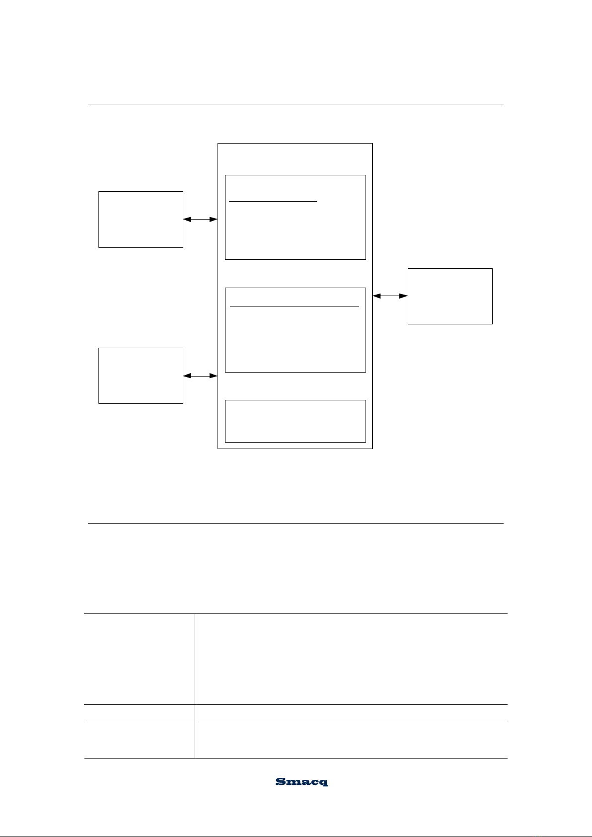
1.2. Function Diagram
Figure 1.1 shows the schematic diagram of USB-5200 series data acquisition device.
Digital system
USB bus
Trigger source:
Software trigger
External trigger
Din trigger
Sampling clock source:
Internal module sampling
clock source
External sampling clock
source
AI
Digital I/O
FIFI cache
Figure 1.1 USB-5200 series data acquisition device functions
1.3. Product specifications
The following product specification parameters, unless otherwise stated, are acquired at
the temperature of 25°C and the humidity of 40%, while the device is turned on for 20
minutes.
Analog input
Number of channels
USB-5220/5221: 16Single-Ended
USB-5210/5211: 8Single-Ended
USB-5620/5621: 16Single-Ended
USB-5610/5611: 8Single-Ended
USB-5420/5421: 8Single-Ended
USB-5410/5411: 8Single-Ended
ADC type SAR
Resolution USB-5220/5221/5210/5211: 16-bit
USB-5620/5621/5610/5611: 14-bit
9 |
USB-5420/5421/5410/5411:12-bit
Highest sampling rate
USB-5211/5221: 500
USB-5210/5220: 250
USB-5611/5621: 500
USB-5610/5620: 250
USB-5411/5421: 500
kS/s/Ch,continuous
kS/s/Ch,continuous
kS/s/Ch,continuous
kS/s/Ch,continuous
kS/s/Ch,continuous
USB-5410/5420: 250kS/s/Ch,continuous
Timing resolution 10ns
Channel synchronization Yes
Range ±10 V / ±5V
Input coupling mode DC
Input impedance 100 MΩ
Small signal bandwidth
(-3 dB)
Input bias current 1uA
Analog input
max voltage ±1 5 V
Software FIFO 2 MPts/Ch
Pre-trigger FIFO 4096 Pts
AI capture mode Continuous acquisition mode and limited number acquisition mode
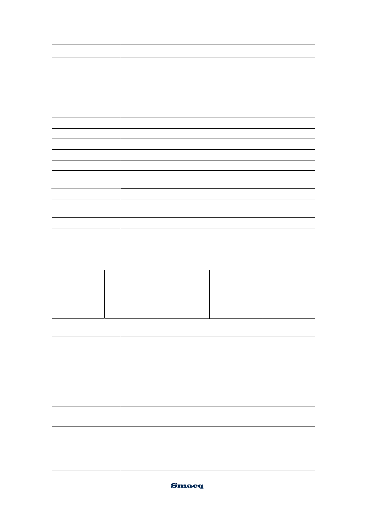
Analog input accuracy (with temperature coefficient of 5 ppm/℃)
Range Gain error
(ppm of reading)
Offset error
(ppm of range)
Random noise
(μVrms)
Full range
absolute accuracy
(μV)
±10 V90 4180 1100
±5 V80 10 90 500
Digital I/O
Number of channels USB-5210/5211/5610/5611/5410/5411: 8 input,8 output
USB-5220/5221/5620/5621/5420/5421: 2 input,2 output
Ground reference DGND
10 kΩ
Digital input pull-up
resistanc
Digital input voltage High level:1.95 V~5 V
Low level:0 V~1.2 V
Digital output voltage High level:3.3 V
Low level:0 V~0.003 V
Low level
Digital output
power-on status
10 MS/s/Ch
450 kHz
DIN highest
sampling rate
Ce manuel convient aux modèles suivants
12
Table des matières
Autres manuels Smacq Technologies Stockage


Manuels Stockage populaires d'autres marques


Spectra Logic
Spectra Logic T-Series Spectra T50e Manuel utilisateur

Panasonic
Panasonic LKM-F931-1 Manuel utilisateur

Tabernus
Tabernus Enterprise Erase E2400 Manuel utilisateur

Rocstor
Rocstor COMMANDER 3F series Manuel utilisateur

HP
HP P9000 Manuel utilisateur

Western Digital
Western Digital Ultrastar Data60 Manuel utilisateur