Skanti VHF 1000 P DSC Manuel utilisateur
Operator’s
Manual
SKANTI
VHF 1000 DSC
Professional VHF
with built-in DSC
ii
DISTRESS Call
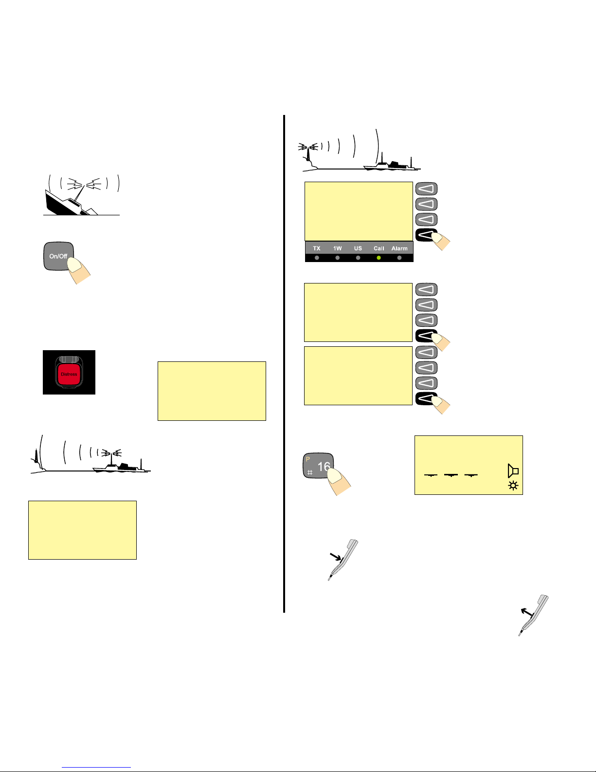
Quick DISTRESS Call
1. If off or UNIT OFF: press ON/OFF.
2. Open DISTRESS lid.
3. Press DISTRESS until RELEASE is displayed.
This takes 5 seconds, during which the indicator lamps TX and
ALARM will flash
Wait
for answer!
(The distress call is auto-
repeated every 3.5-4.5 minutes.)
Acknowledgment
4. Press VIEW.
Press the DISTRESS button
for 5seconds to transmit
TYPE : Distress
MSG. : Undesignated
Pos : N:05°01E:009°54
Time : 18.12 UTC CANCEL
Call contents
first page
Time: 18.22.06 19 Aug 97
TYPE : All station
FROM: 002191000
CAT : Distress
ACK : Call MORE View next page.
Call contents CONNECT
second page
COMM: Distress ackn
SHIP : 123456789
MSG. : Undesignated
Pos : N:05°01E:009°54 AGAIN View call again.
Mayday Procedure
5. Press “16”.
6. Lift handset. Press PTT and say:
“MAYDAY, MAYDAY, MAYDAY
This is <Ship name (3 times)>
MAYDAY
This is <Ship name + call sign>
Position:......
What is wrong:.....
Kind of assistance:......
Number of crew:.....
Other info:....
OVER.”
Release PTT and
listen for answer.
Press
Release
5 - 4 - 3 - 2 - 1 - RELEASE
2 13 06
25W
INT
MEM VOL SQ
16
Waiting for
Distress
Acknowledgment
Retransmit distress
call every 4 minutes CANCEL
16
Read call contents.
Distress
acknowledg-
ment received
FROM: 002191000 VIEW
NB! DISTRESS is only to be used in case of
an emergency!
iii
14 13 12 11 10 9
1
2
3
85746
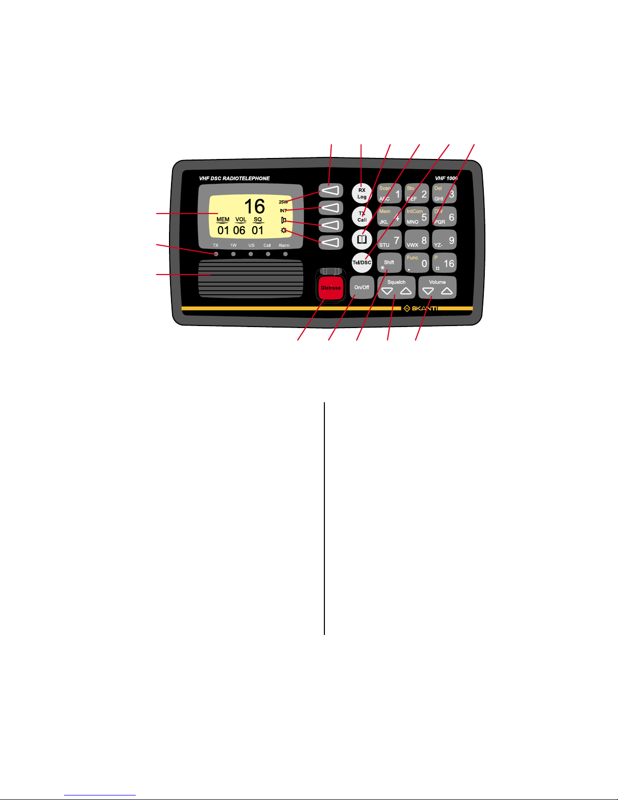
What is What?
1. Display.
2. Indicator lamps. Condition when lit:
Tx: Transmitting.
1W: 1 watt transmission mode.
US: US channel system activated.
(For information on the BI version, see p.11).
CALL: DSC (see button 10) call for you received.
ALARM: Alarm call received.
3. Loudspeaker.
4. Squelch control. Adjust to silent when no station is received.
5. ON/OFF push button.
6. Volume control.
7. Shift key. Press and hold for yellow functions.
8. DISTRESS button, protected by shield. To use, lift the shield and
press for 3 seconds, guided by the text displayed.
9. Keyboard.
10. TEL/DSC function switch.
In TELmode radiotelephone parameters are shown and
selected.
In DSC mode DSC parameters are shown and selected.
11. Open the ADDR BOOK in DSC mode.
12. Tx CALL: Press to start creating a DSC call.
13. Open the Rx log of received calls in DSC mode.
14. Display keys. The function of each key is described in its
respective line on the right side of the display.
Abbreviations Used in this
Manual
ADDR Address
ATIS Automatic Transmitter Identification System
BI Channel mode used when sailing on European rivers
(more details on p. 11)
DSC Digital Selective Calling
DUP Duplex
DW Dual Watch
GMDSS Global Maritime Distress and Safety System
GPS Global Positioning System
LF Low Frequency
MEM Memory
MMSI Maritime Mobile Ship Identification
MSG Message
PTT Push-To-Talk
RX Receive(r)
SQ Squelch
STN Station
TEL Telephony
TX Transmit(ter)
UTC Coordinated Universal Time

iv
About this Manual
This manual is for the daily user of the system. The manual includes
two main sections, “basic” operation and “full” operation. The basic
part offers a short easily-read description of the main functions; the
full part offers elaborate descriptions of the functions of the product.
Please note
Any responsibility or liability for loss or damage in connection with
the use of this product and the accompanying documentation is dis-
claimed. The information in this manual is furnished for informational
use only, is subject to change without notice, may contain errors or
inaccuracies, and represents no commitment whatsoever. This
agreement is governed by the laws of Denmark.
Doc. No.: B4830GB9 Issue: F/9945
Introduction
The SKANTI VHF 1000 DSC is the new VHF radio for merchant
vessels, fishing ships and other professional users. The SKANTI
VHF 1000 DSC fulfils the latest requirements for VHF and DSC
(digital selective calling function) Class A, and is thus ideal for safe
communication.
The SKANTI VHF 1000 is a professional VHF and an advanced DSC
unit (Class A) integrated in one compact unit, which is ideal for
vessels with limited space for multi-unit configurations. The integra-
tion of the VHF and the DSC functionality ensures simple and logical
operation of the mandatory VHF and DSC GMDSS equipment.
The ergonomic control unit (CU 1000) with an easily legible graphic
LCD display ensures all-time operation. The back-lit “easy-touch”
keyboard makes operation extremely easy even during night time.
The user-friendliness of the operational software facilitates the use of
the two functions: VHF and DSC, which are integrated into one unit.
The control unit includes a built-in loudspeaker of 4 watt and the
important DSC distress button, which is covered by a hatch for the
prevention of unintentional activation. The ergonomically correct
handset is integrated in the control unit securing a complete VHF/
DSC communication platform.
For easy installation the control unit is mounted on the compact
VHF/DSC transceiver unit which has an output power of 25 watt,
thus being able to reach all VHF stations within 40-50 nautical miles.
The VHF includes a SPARC-bus interface. This advanced interface
enables the VHF 1000 DSC to be remote-controlled from handsets
placed e.g. on the bridge wings.
The distance between the transceiver unit and the handset control
unit may be up to 50 metres in 12V DC installations; in 24V DC
installations the distance may be up to 100 metres. An external
loudspeaker may be connected directly to the handset control unit.

1
Contents
DISTRESS Call ..................................................................... ii
Quick DISTRESS Call ..................................................... ii
Acknowledgment.............................................................. ii
Mayday Procedure........................................................... ii
What is What? ..................................................................... iii
Abbreviations Used in this Manual .................................. iii
Introduction......................................................................... iv
About this Manual .............................................................. iv
VHF Fundamental Info ........................................................ 2
The VHF Channel System ............................................... 2
Verbal VHF Communication ............................................ 2
DSC Digital Communication ............................................ 2
Basic Operation ................................................................... 3
Switching ON/OFF ........................................................... 3
Basic Telephony Operation ................................................ 3
Listening for Telephony Calls........................................... 3
Receiving a Telephony Call ............................................. 4
Making a Telephony Call.................................................. 4
Channel Control ............................................................... 5
Squelch Control ............................................................... 5
Setting the Volume Level ................................................. 6
Setting Transmitter Power Level...................................... 6
Muting the Speaker.......................................................... 6
Dimmer Function.............................................................. 6
Basic DSC Operation .......................................................... 7
DSC Main Buttons ........................................................... 7
DSC Display Operation.................................................... 7
Calling a SHIP.................................................................. 8
Receiving an Individual Call ............................................ 8
Calling a SHORE Station................................................. 9
Calling a PHONE NUMBER Directly ............................... 9
The ADDR BOOK ............................................................... 10
The Rx LOG ........................................................................ 10
Full Operation .................................................................... 11
Full VHF Telephony Operation ......................................... 11
Setting Channel Mode ................................................... 11
Setting International/US Channel Mode ........................ 11
Setting International/BI Channel Mode.......................... 11
25W Transmitter Power Level ....................................... 11
Setting Memory Scan Table........................................... 12
Scanning of Channels.................................................... 12
Dual Watch..................................................................... 14
Intercom ......................................................................... 15
Full DSC Operation............................................................ 17
Receiving DSC Calls...................................................... 17
TX CALL Menu............................................................... 18
Tone signalling when receiving DSC Calls..................... 20
Function MENU .................................................................. 21
Changing a Function...................................................... 21
Functions Tree ............................................................... 22
VHF System Description................................................... 23
International Channels...................................................... 24
US Channels....................................................................... 25
BI Channels ........................................................................ 26
2
VHF Fundamental Info
The VHF Channel System
The VHF radio telephony system uses a limited number of frequen-
cies called channels. The public system has 57 channels, numbered
CH 1 to 28 and 60 to 88, each of which has a certain purpose:
intership, ship-to-port, or ship-to shore (public). You can have private
channels, too. In US waters, the channels are different. Therefore
you need to set the system to “US” channels there. Other waters like
the Rhine have their own different systems, too.
Four channels have special purposes:
16: To be used for verbal distress calls and for calling “all
stations”
only
. All large ships are obliged to monitor it
constantly. Never to be used for chatting, etc.!
70: The DSC channel, see below.
75-76: Used as Guard Band for distress channel 16.
Verbal VHF Communication
All channels except channel 70 are used for verbal communication.
There are two types of channels, simplex and duplex:
- On a simplex channel, both parties transmit and receive on the
same frequency. Therefore you cannot talk and listen at the
same time. When you have finished talking, say “over”, and
release the handset’s PTT key.
- On a duplex channel, you talk and listen on two different
frequencies. You can therefore speak and listen at the same
time. To save power, release the handset’s PTT key except when
talking.
Note that everybody with a VHF receiver can listen to your conversa-
tion, but it is forbidden to use or pass on what is heard.
DSC Digital Communication
DSC is a digital data transfer system using VHF CH 70. The
transmitter waits until the channel is free and then sends its data,
either to a designated address, or to “all stations” for example for a
DSC distress call. It is mainly used for getting in contact in order to
establish verbal communication.
Telephony display
Normal display
Scanning display
DUP 25W
DW INT
MEM VOL SQ
12
1 10 03
TX Power indicator
INT/US mode indication
Speaker On/Off
Dimmer
25W
INT
MEM P-CH
Pr -
7 ALL 16
3
Basic Operation
Switching ON/OFF
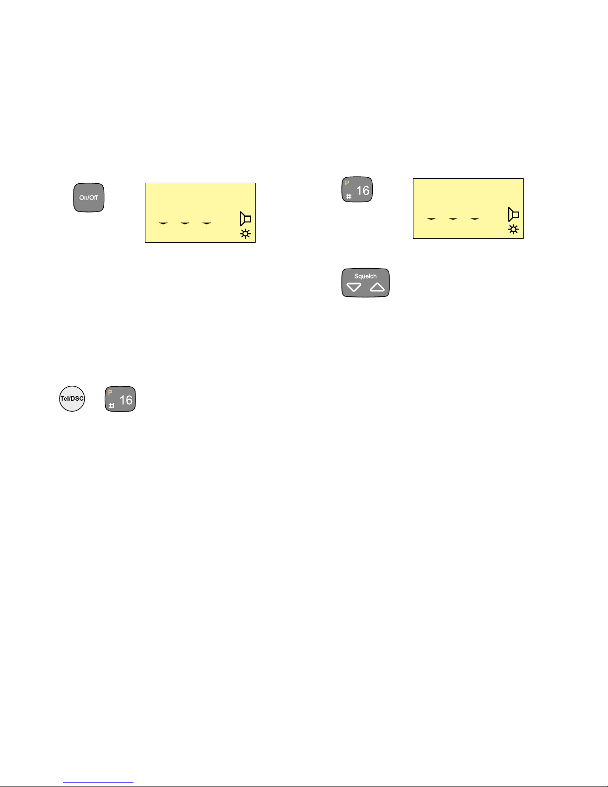
1. Press the ON/OFF button.
In UNIT OFF mode, the VHF set is remote controlled.
To activate the panel, press ON/OFF.
Basic Telephony Operation
To activate the VHF functions if not active press the key
TEL/DSC or the key “16”.
or
Listening for Telephony Calls
According to international rules, all ships shall monitor channel 16
constantly:
1. Select channel 16 by pressing:
2. Set the squelch level by means of the button
a. Step down squelch level until noise is heard on free channel.
b. Then step up to the first level where just silent.
(To listen for calls on other channels, select the channel number
or use the scanning facility.)
25W
INT
MEM VOL SQ
16
1 10 03
25W
INT
MEM VOL SQ
16
1 10 03
4
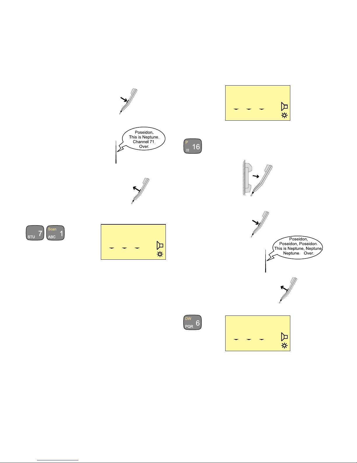
Receiving a Telephony Call
When a call comes in, and your call name is heard in the loud-
speaker:
1. Hook off the handset.
2. Press the PTT key on the handset.
3. To answer the call, say:
“<The name of the calling station>
This is <Your station name>“
4. To suggest channel, say:
“Channel” <suggested channel number>”
5. Say “over” and release the PTT key
to let the caller accept the
proposed channel number.
6. Switch to the channel aggreed upon (for example channel 71)
and communicate:
Press the PTT key when talking only. If on a simplex channel, say
“over” every time you have completed talking.
Press
Release
25W
INT
MEM VOL SQ
71
6 10 03
Making a Telephony Call
In telephony mode:
1. Select channel 16 or another channel specified or agreed upon:
2. Hook off the handset.
3. When speaking,
press the handset PTT key.
Make the call:
1. <Called station name (3 times)>
2. “This is “
<Your station name (3 times)>
3. “Over”
4. Release the PTT key to listen.
5. When answered,
agree upon a channel,
switch to the channel (for example channel 6) and communicate.
Press the PTT key when talking only. If on a simplex channel,
say “over” every time you have completed talking.
Press
Release
25W
INT
MEM VOL SQ
71
6 10 03
25W
INT
MEM VOL SQ
6
6 10 03
5
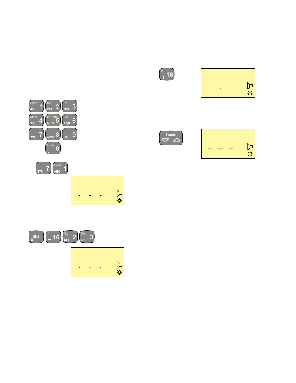
Channel Control
Setting the VHF channel can be done in two ways by means of the
numeric input keys or by using the quick select key “16”:
Numeric keys:
Press the numeric input keys until the desired channel number is
shown on the display:
Ex:
If private channels are available in your VHF system, a private
channel number is selected by pushing the buttons:
Ex: Private channel 23
25W
INT
MEM VOL SQ
71
0 10 03
25W
INT
MEM VOL SQ
P23
0 09 01
25W
INT
MEM VOL SQ
16
0 10 03
Squelch Control
Set the squelch sensitivity of the receiver by the button
The squelch setting is shown on the display below the “SQ” symbol.
25W
INT
MEM VOL SQ
6
1 08 02
Quick select key:
Press the key
6
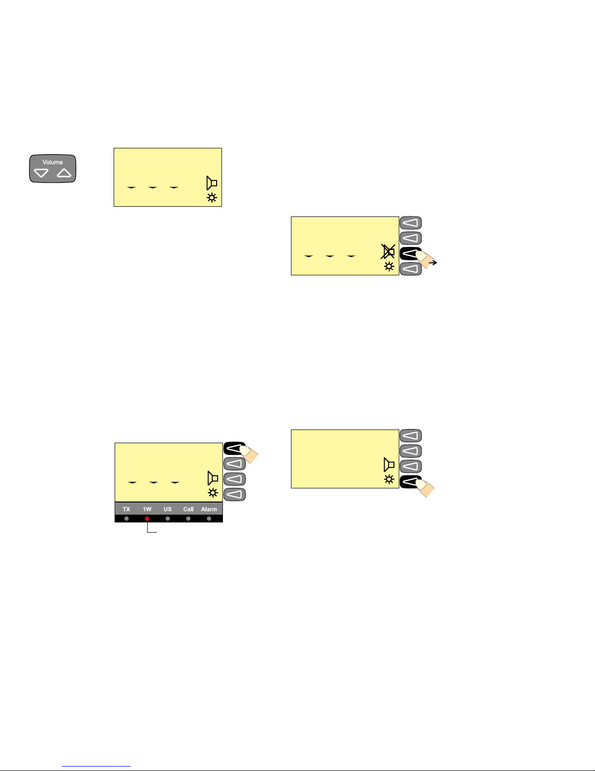
Setting the Volume Level
To change the volume setting use
The volume setting is shown on the display below “VOL”.
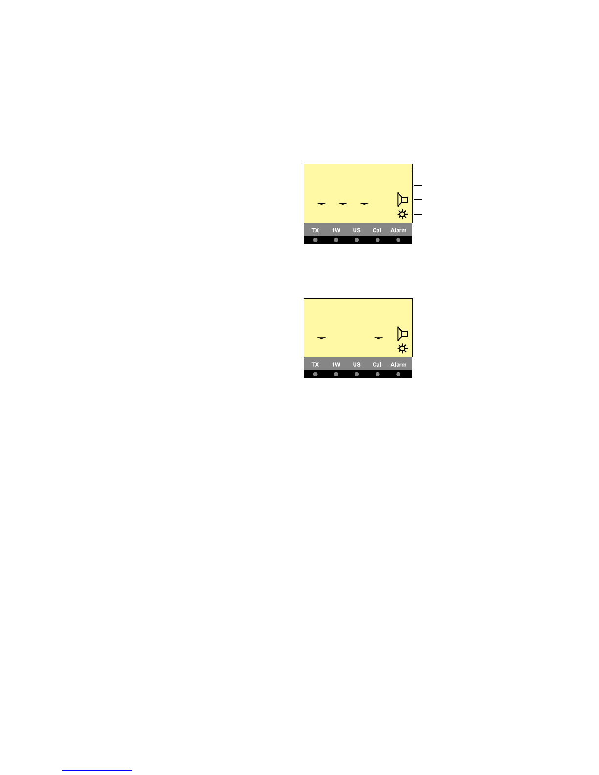
Muting the Speaker
If the speaker is active, it is automatically muted when the PTT is
pressed, and then reactivated when the PTT is released.
The speaker icon on the display shows the speaker state.
Speaker active:
To mute or unmute the speaker, press the soft key
Setting Transmitter Power Level
The VHF set can control the transmitter power level, which can be
set to either 1W or 25W.
Low power 1W is indicated by the indicator lamp on the display.
Some channels may be programmed to operate at 1W level only.
To change the TX power level press the soft key.
Dimmer Function
The VHF set features display backlight, keyboard backlight
and light in the indicator lamps (TX, 1W, US, CALL and ALARM).
The light can be set in four steps 0-3.
To change the dimmer level press the soft key
When the key is being pressed the dimmer level will change every
second.
25W
INT
MEM VOL SQ
6
1 10 01
1W indicator lamp
1W
INT
MEM VOL SQ
6
1 08 04
25W
INT
MEM VOL SQ
6
1 00 04 Speaker muted
25W
INT
6
LEVEL 2
Autres manuels pour VHF 1000 P DSC
1
Table des matières
Manuels Émetteur populaires d'autres marques


Dejero
Dejero EnGo 3x Manuel utilisateur

Rosemount
Rosemount 4600 Manuel utilisateur

Speaka Professional
Speaka Professional 2342740 Manuel utilisateur

trubomat
trubomat GAB 1000 Manuel utilisateur

Teledyne Analytical Instruments
Teledyne Analytical Instruments LXT-380 Manuel utilisateur

Rondish
Rondish UT-11 Manuel utilisateur


