Servo Dynamics 1525-BRS Manuel utilisateur
1525-BRS
SERVO DRIVE
FOR BRUSH SERVOMOTORS
USER GUIDE
September 2004

DynaDrive 1525-BRS - User Guide Page 2
Important Notice
This document is subject to the following conditions and restrictions:
• This document contains proprietary information belonging to Servo Dynamics. This
information is provided for the purpose of assisting users of the servo drive in its
installation.
• The text and graphics in this document are for the purpose of illustration and reference
only.
• The information in this document is subject to change without notice.
Revision History:
Version 1.01: September 27, 2004
Version 1.00: October 4, 2000

Contents
DynaDrive 1525-BRS - User Guide Page 3
1. Introduction........................................................................................................................... 4
1.1 Description...................................................................................................................... 4
1.2 Technical Specifications ................................................................................................. 5
2. Safety Information................................................................................................................ 6
2.1 Electrical Cautions.......................................................................................................... 6
3. Installation............................................................................................................................. 7
3.1 Matching the DynoDrive to the Motor ........................................................................... 7
3.2 Mounting Dimensions..................................................................................................... 8
3.3 Connector Information.................................................................................................... 9
3.3.1 J1 – Control I/O Connection ................................................................................................... 9
3.3.2 J2 - Servomotor Connection.................................................................................................. 10
3.4 Wiring Diagram ............................................................................................................ 11
3.4.1 DynaDrive 1525-BRS and Motor with Encoder ................................................................... 11
3.5 Potentiometers -Adjustments........................................................................................ 12
4. Operational Modes.............................................................................................................. 13
4.1 Torque Mode................................................................................................................. 13
4.1.1 Torque Mode – Factory Potentiometer Settings....................................................................13
4.1.2 Torque Mode - Setup ............................................................................................................14
4.2 Velocity Mode .............................................................................................................. 15
4.2.1 Velocity Mode – Factory Potentiometer Setting ................................................................... 15
4.2.2 Velocity Mode- Setup ........................................................................................................... 16
5. Troubleshooting .................................................................................................................. 17
5.1 Diagnostic LEDs........................................................................................................... 17
5.1.1 Green LED ............................................................................................................................ 17
5.1.2 Red LEDs:............................................................................................................................. 17
5.2 Other Conditions........................................................................................................... 18
5.3 Test Points..................................................................................................................... 18
5.4 Contact Information ...................................................................................................... 19

Introduction
DynaDrive 1525-BRS - User Guide Page 4
1. Introduction
This information manual provides the product specifications, wiring diagram, operational modes
(torque and velocity) and troubleshooting procedures for the brush DynaDrive 1525-BRS.
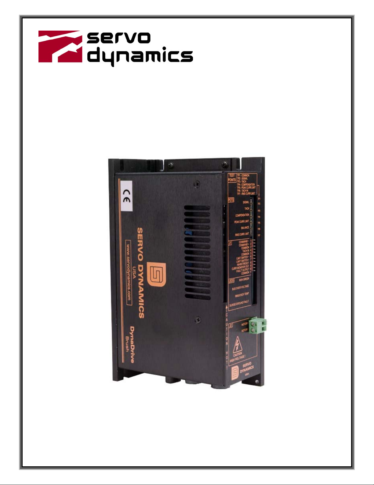
1.1 Description
The DynaDrive 1525-BRS supplies 15 amps continuous current and 25 amps peak current at 164
VDC for a total of 2460 watts of continuous power. The DynaDrive is a current source type
PWM amplifier.
The DynaDrive is a power duplicator of the command signal. A battery, a motion controller, or a
signal generator can be the source of the command signal input.
Please read this manual thoroughly to the end as it contains important system information
and warnings.

Introduction
DynaDrive 1525-BRS - User Guide Page 5
1.2 Technical Specifications
Performance Characteristics
Peak Power 4.1 kW
Peak Output Voltage ± 164 vdc (shut off @ 205 vdc)
Peak Output Current ± 25 amps (1 sec.)
Max. Continuous Current ± 15 amps (50 °C), ± 19 amps (25 °C)
Internal Shunt Regulator 55 W continuous, 2.4 kW peak for .02 seconds
(activates at 190 vdc)
Electrical Characteristics
Input Signal Voltage ± 10 vdc (typ.),
± 35 vdc (max.)
System Gain 0 to 10,000 amps/volt
Input Impedance 40 k Ohms
Typical Input Drift 10 µV/°C
Bandwidth 2 kHz with 1.2 mH Inductance
Dead Band Zero
Input Power Requirements
Input Voltage 45 - 120 vac
Adjustments
Peak Current Limit 0 to 25 amps
RMS Current Limit 0 to 19 amps
Signal Command Input Scaling
Balance Zero velocity offset
Compensation System response
Tachometer Scaling
Diagnostics LED indication
Red LED 1 – RUN GREEN - AMPLIFIER OPERATIONAL
Red LED 2 – BUS OVER VOLTAGE
Red LED 3 – EXCESSIVE RMS CURRENT/ OVER TEMP
Green LED 4 – SURGE/GROUND FAULT
Physical Characteristics
Module Dimensions (L x W x H) 7.6 in. x 2.5 in. x 4.7 in.
Weight 2.4 lbs
Ambient Temperature – Operating 0 °C to 50 °C
Shutdown Temperature 80 °C at heat sink
Relative Humidity 5 - 95% non-condensing
Table 1: Technical Specifications for DynaDrive 815 – BR-3

Safety Information
DynaDrive 1525-BRS - User Guide Page 6
2. Safety Information
2.1 Electrical Cautions
Make sure that all voltages and tests are made with battery powered or electrically isolated
instruments.
Installation
DynaDrive 1525-BRS - User Guide Page 7
3. Installation
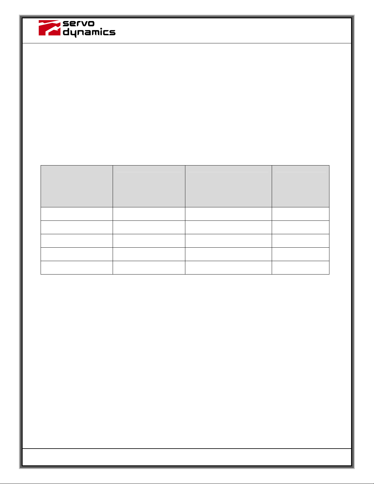
3.1 Matching the DynoDrive to the Motor
The factory preset potentiometer settings of the DynaDrive 1525-BRS may need to be adjusted
to match the continuous current rating of your motor. To accomplish this, find the continuous
current rating of the motor to be used and adjust the RMS, PEAK CURR LIMIT and SIGNAL
pot per Table 2 below. If the continuous current rating is between the values shown in the table,
you may set to the lower value or use linear interpolation for each pot value. The signal pot
settings are based on +/- 10 vdc input command signal. Remember that all resistance
measurements must be made with power off and J1 disconnected.
Continuous Current
Rating of Motor
(Amps)
RMS
Pot Setting
TP7
K Ohms (Amps)
PEAK CURRENT LIMIT Pot
Setting
TP5
K Ohms (Amps)
SIGNAL
Pot Setting
TP2
K Ohms
3 4.0 (3 Amps) 0.7 (9 Amps) 2.0
6 6.6 (6 Amps) 1.6 (18 Amps) 3.8
9 8.9 (9 Amps) 2.2 (25 Amps) 4.8
12 10.5 (12 Amps) 2.2 (25 Amps) 4.8
15 11.6 (15 Amps) 2.2 (25 Amps) 4.8
Table 2: Motor Specs
Note: All Measurements are with respect to TP1 (Common) with J1 removed.

Installation
DynaDrive 1525-BRS - User Guide Page 8
3.2 Mounting Dimensions
Note: Units in inch

Installation
DynaDrive 1525-BRS - User Guide Page 9
3.3 Connector Information
3.3.1 J1 – Control I/O Connection
J1 Label Description
1 COMMAND - Differential input
2 COMMAND + Differential input. This pin can also be used as a single ended
input. Use J1, pin 2 as common.
3 COMMON Connected to other commons and connected to the metalwork of
the amplifier mounting plate.
4 TACH IN Single ended input that has additional tach filtering and
conditioning.
5 COMMON See pin 3 above.
6 LIMIT SWITCH - Prevents motor overtravel in the CCW direction. Normally open,
unless J4 is installed
7 LIMIT SWITCH + Prevents motor overtravel in the CW direction. Normally open,
unless J4 is installed.
8 INHIBIT/RESET Internally pulled to + 12Vdc. Pull to common to inhibit and reset
amplifier.
9 CURR MONITOR OUT Current monitor output. +/- 4 VDC out equals approx. +/- 25
amps.
10 FAULT OUTPUT Normally pulled up to +12 volts thru a 10 K resistor. Will sink 10
mA max to ground when a fault occurs.
11 COMMON See pin 3 above.
Installation
DynaDrive 1525-BRS - User Guide Page 10
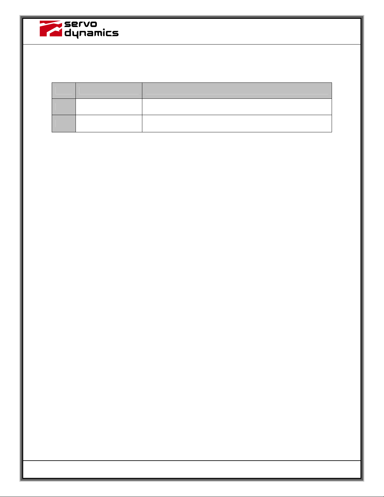
3.3.2 J2 - Servomotor Connection
J2 Label Description
1 MOTOR + Output power to motor
2 MOTOR - Output power to motor
Table des matières
Autres manuels Servo Dynamics servomoteur

Manuels servomoteur populaires d'autres marques

Mitsubishi Electric
Mitsubishi Electric MELSERVO-J5 MR-J5-G Series Manuel utilisateur

Robotis
Robotis XH430-W350-T Manuel utilisateur

NTI AG
NTI AG LinMot C1250 Series Manuel utilisateur

Welcon
Welcon WE2A D048 Series Manuel utilisateur

Parallax
Parallax 900-00005 Manuel utilisateur

Festo
Festo TP 1410 Manuel utilisateur


