Pegatron IPPSB-DB Manuel utilisateur

Mainboard User Guide
IPPSB-DB

2IPPSB-DB Mainboard User Guide
Contents
Contents....................................................................................2
Introduction...............................................................................3
Hardware Specications..........................................................4
Mainboard Layout.....................................................................5
Top view ....................................................................................................... 5
Components................................................................................................. 6
Selectors ...................................................................................7
Clear CMOS selector (A20/Pitch 2.54mm)................................................. 7
Intel Management Engine selector (A29/Pitch 2.54mm) .......................... 7
Connectors................................................................................8
2.5” HDD connector (A1/Pitch 1.27mm) .................................................... 8
ODD Power connector (A2/Pitch 2.0mm) .................................................. 8
SATA HDD Power connector (A3/Pitch 2.0mm) ........................................ 9
SATA connector (A4 and A33/Pitch 1.27mm)............................................ 9
CPU fan2 connector (A5/Pitch 1.25mm).................................................. 10
System fan connector (A6/Pitch 1.25mm)............................................... 10
Panel inverter connector (A7/Pitch 2.0mm) .............................................11
LVDS connector (A9/Pitch 1.0mm) ...........................................................11
Power button/Power LED/Volume control connector
(A10/Pitch 1.0mm) ..................................................................................... 12
EDID connector (A12/Pitch 1.25mm) ....................................................... 12
Webcam+DMIC connector (A13/Pitch 1.0mm)........................................ 13
Wireless slot (A16/Pitch 0.8mm) .............................................................. 14
LCD mode switch/HD LED/Brightness control connector
(A18/Pitch 1.0mm) ..................................................................................... 15
Card Reader (A19) ..................................................................................... 15
Speaker connector (A23/Pitch 1.25mm).................................................. 16
RF connector (A24/Pitch 1.5mm) ............................................................. 16
IR connector (A25/Pitch 1.25mm) ............................................................ 17
TV tuner slot (A26/Pitch 0.8mm) .............................................................. 18
Low Pin Count connector (for Debug Card) (A28/Pitch 0.5mm) .......... 19

IPPSB-DB Mainboard User Guide 3
“This is the optimally designed mainboard for All-In-One devices which
supports 6 USB ports, VGA Input, Mic input, Audio output, LAN (RJ-45) port,
Memory card reader, 2.5”/3.5” HDD SATA port, ODD SATA port, Webcam,
Speakers, TV tuner, WLAN, RF, IR. The mainboard has a layout specialized
for thermal design and ID structure.”
Introduction
4IPPSB-DB Mainboard User Guide
Hardware Specications
CPU
Socket: Intel Socket 1155
Supports : Sandy bridge
TDP : 65W
Chipset
South Bridge : Intel H61
Memory
Dual Channel, 2 slots, Non-ECC, Unbuffered,
204 pin DDR3 SODIMM, Max. 16GB
Types:
1066/PC3-8500, 1333/PC3-10600
Storage
3x SATA ports, SATA300/150
LAN
Gigabit : Realtek RTL8111E-VL
USB
6x USB ports (2x ports convertible to USB 3.0)
Graphics
Integrated Graphics
Audio
Realtek ALC663 (2-channel)
Rear panel I/O ports
1x ATX power port
1x LAN (RJ-45) port
1x Line_out port (convertible to HDMI Out port)
1x Display (VGA In) port
4x USB 2.0 ports
Side panel I/O ports
2x Audio jacks (2-channel)
1x USB 2.0 port (convertible to USB 3.0)
1x USB 2.0 port (convertible to USB 3.0)
1x Card reader port
Internal connectors
1x 2.5” HDD connector (A1/Pitch 1.27mm)
1x ODD Power connector (A2/Pitch 2.0mm) (5V) for slim-ODD or 2.5” HDD
1x SATA HDD Power connector (A3/Pitch 2.0mm) (5V/12V) for 3.5” HDD
2x SATA connectors (A4 and A33/Pitch 1.27mm)
1x CPU fan2 connectors (A5/Pitch 1.25mm) (12V)
1x System fan connector (A6/Pitch 1.25mm) (12V)
1x Panel inverter connector (A7/Pitch 2.0mm)
1x LVDS connector (A9/Pitch 1.0mm)
1x Power button/Power LED/Volume control connector (A10/Pitch 1.0mm)
1x EDID connector (A12/Pitch 1.25mm)
1x Webcam + DMIC connector (A13/Pitch 1.0mm)
1x Wireless slot (A16/Pitch 0.8mm)
1x LCD mode/HD LED/Brightness control connector (A18/Pitch 1.0mm)
1x Card Reader (A19)
1x Speaker connector (A23/Pitch 1.25mm)
1x RF connector (A24/Pitch 1.5mm)
1x IR connector (A25/Pitch 1.25mm)
1x TV tuner slot (A26/Pitch 0.8mm)
1x Low Pin Count connector (for Debug Card) (A28/Pitch 0.5mm)
BIOS
AMI 32Mb (SPI)
Form factor
Proprietary, 7.90 inches x 9.05 inches
IPPSB-DB Mainboard User Guide 5
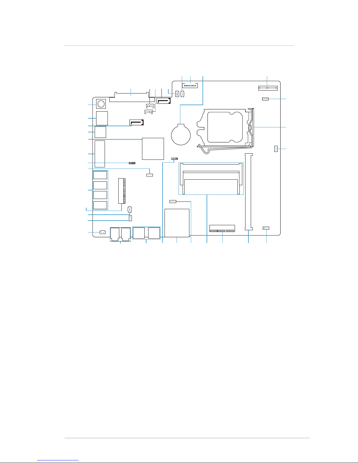
Mainboard Layout
Top view
A1 A2 A3 A4 A5
A7A6 A8 A9
A11
A10
A12
A13A14A16A17
(USB3.0
optional)
A18A19A20A21A22
A24
A23
A25
A26
A27
A28
A29
A30
A32
A31
A33
A34
A35
(HDMI
optional)

6IPPSB-DB Mainboard User Guide
Components
Mainboard Layout
*These components do not have pin denitions shown in this document.
No. Name No. Name No. Name
A1 2.5” HDD
connector
A13 Webcam+DMIC
connector
A26 TV tuner slot
A2 ODD Power
connector
A14* Mini PCI-E slot
(x16)
A27* USB 2.0 ports
A3 SATA HDD
Power
connector
A16 Wireless slot A28 Low Pin Count
connector
(for Debug Card)
A4 SATA connector A17* Memory
sockets
A29 Intel
Management
Engine selector
A5 CPU fan2
connector
A18 LCD mode
switch/HD LED/
Brightness
control connector
A30* VGA In port
A6 System fan
connector
A19 Card reader A31* Intel Platform
Controller Hub
A7 Panel inverter
connector
A20 Clear CMOS
selector
A32* Line_out port
(convertible to
HDMI Out port)
A8* Battery A21* USB 2.0 ports
(convertible to
USB 3.0 ports)
A33 SATA connector
A9 LVDS connector A22* Audio jacks A34* LAN (RJ-45)
port
A10 Power button/
Power LED/
Volume control
connector
A23 Speaker
connector
A35* ATX power port
A11* Intel Socket 1155
CPU Socket
A24 RF connector
A12 EDID
connector
A25 IR connector

IPPSB-DB Mainboard User Guide 7
Selectors
Settings:
[2-3] Normal [1-2] Flash override
Intel Management Engine selector (A29/Pitch 2.54mm)
Pin Signal Name Pin Signal Name
1 HDA_SDO 3 NC
2 +3P3VSB
Settings:
[1-2] Normal [2-3] Clear CMOS
Clear CMOS selector (A20/Pitch 2.54mm)
Pin Signal Name Pin Signal Name
1 N/C 3 GND
2 RTC_RST#

8IPPSB-DB Mainboard User Guide
2.5” HDD connector (A1/Pitch 1.27mm)
Pin Signal Name Pin Signal Name Pin Signal Name
1 GND 10 +3P3V 19 GND
2 SATA_TXP0_C 11 GND 20 +12V
3 SATA_TXN0_C 12 GND 21 +12V
4 GND 13 GND 22 +12V
5 SATA_RXN0_C 14 +5V 23
6 SATA_RXP0_C 15 +5V 24
7 GND 16 +5V 25
8 +3P3V 17 GND 26
9 +3P3V 18 GND
ODD Power connector (A2/Pitch 2.0mm)
Connectors
Pin Signal Name Pin Signal Name
1 +5V 3 GND
2 +5V 4 GND

IPPSB-DB Mainboard User Guide 9
Connectors
SATA connector (A4 and A33/Pitch 1.27mm)
SATA HDD Power connector (A3/Pitch 2.0mm)
Pin Signal Name Pin Signal Name
1 +5V 3 GND
2 GND 4 +12V
Pin Signal Name Pin Signal Name Pin Signal Name
1 GND 4 GND 7 GND
2 SATA_TXP1 5 SATA_RXN1 8 NC
3 SATA_TXN1 6 SATA_RXP1 9 NC

10 IPPSB-DB Mainboard User Guide
Connectors
System fan connector (A6/Pitch 1.25mm)
Pin Signal Name Pin Signal Name
1 GND 3 System_FAN_TACH
2 +12V 4 System_FAN_PWM
Pin Signal Name Pin Signal Name
1 GND 3 CPU_FAN_TACH
2 +12V 4 CPU_FAN_PWM
CPU fan2 connector (A5/Pitch 1.25mm)
Table des matières
Autres manuels Pegatron Carte mère


Manuels Carte mère populaires d'autres marques


Telit Wireless Solutions
Telit Wireless Solutions SL869-3DR Manuel utilisateur

Gigabyte
Gigabyte GA-9IVDT Manuel utilisateur

Texas Instruments
Texas Instruments ADS8372EVM Manuel utilisateur

Commell
Commell MS-C73 Manuel utilisateur

IBT Technologies
IBT Technologies MB860 Manuel utilisateur

Nvidia
Nvidia TEGRA DG-04927-001_V01 Manuel utilisateur


