Parktron CPS2000 Manuel utilisateur

CPS2000 Chipcoin Parking System
Entry/Exit Terminal - CENT209/CEXT209
Version 4.0
Issue Date: 2014.01
Installation Manual

2
© 2014 - 2024 Parktron Technology Ltd.
Table of Content
1. Cabinet installation (Entry/Exit Terminal): ....................................................................4
1.1. Shipping package:..................................................................................................4
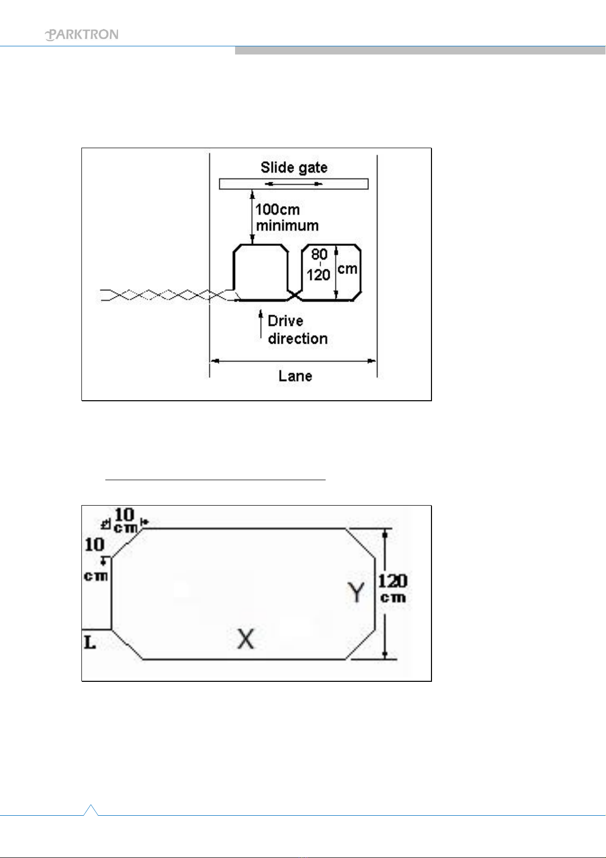
1.2. Foundation island preparation:..............................................................................5
1.2.1. Suggested dimensions: ..............................................................................5
1.2.2. Power, network cable, control signal & intercom wires: .............................6
1.2.3. Anchor bolts: .............................................................................................6
1.3. Detection loop wire installation:............................................................................8
1.3.1. Suggested loop wire specification: .............................................................8
1.3.2. Loop position and wiring guide: .................................................................8
1.3.3. Ground slot cutting for loop wire installation:............................................9
1.3.4. Loop wire installation instruction:............................................................11
2. Cable & wire connection: ............................................................................................12
2.1. Connect loop wires to loop detectors: .................................................................12
2.1.1. Where are loop detectors? ......................................................................12
2.1.2. Loop wire connection to loop detector: ...................................................12
2.1.3. Loop detector configuration & testing: ....................................................13
2.2. Connect barrier gate to terminal: ........................................................................14
2.2.1. Terminal I/O control board wiring contact points reference: ....................14
2.2.2. Barrier gate wiring diagram (for Parktron barrier AGT210):......................16
2.2.3. For other types of barrier:........................................................................18
2.3. DC power outputs of terminal device & signal inputs: .........................................21
2.3.1. Wiring contacts for fixed functions: .........................................................21
2.3.2. Wiring contacts for software programmable functions: ...........................22
2.4. Intercom wiring reference: ..................................................................................23
2.4.1. Wiring diagram example:.........................................................................23
2.4.2. Parktron intercom sub unit: .....................................................................23
2.4.3. Master unit requirement: ........................................................................24
2.5. Network cable connection:..................................................................................24
2.5.1. Connector location: .................................................................................24
2.6. Input power cable connection: ............................................................................25
2.6.1. Terminal input power requirement: .........................................................25
2.6.2. Input power connection location: ............................................................25
3. Power on & configuration: ..........................................................................................26
3.1. Factory default IP addresses: ...............................................................................26
3.2. Preparation for configuration (How to connect terminal with Putty.exe): ............ 26

3
© 2014 - 2024 Parktron Technology Ltd.
3.3. Configure terminal IP address:............................................................................. 27
3.4. Specify terminal program for entry or exit:..........................................................28
3.5. Time synchronization: .........................................................................................29
3.6. Parking system parameters in Parking.ini configuration file: ................................29
3.7. Edit Machine SN ..................................................................................................33
3.8. Terminal software update:...................................................................................33
4. “How to” collection:....................................................................................................34
4.1. How to copy log files: ..........................................................................................34
4.2. How to change terminal time zone:.....................................................................34
4.3. How to set exact terminal date & time: ...............................................................35
4.4. Tips to use Unix editor tool “vi”:..........................................................................35
Revision History:
Version
Released Date
Revision Notes
1.0
2010.02
First edition release
2.0
2010.09
Linux system version 1.0
2.1
2011.08
Add Section 3.2.5.
3.0
2012.11
Content update
3.1
2012.12
Change document format
4.0
2014.01
Change document format

4
© 2014 - 2024 Parktron Technology Ltd.
1. Cabinet installation (Entry/Exit
Terminal):
Make sure all the preparation works in section 1 below are all completed before moving
terminal out of shipping package, and secure terminal to the pre-installed anchor bolts
with nuts, washers and two(2) metal bars come with the shipment onto a proper
position.
1.1. Shipping package:
Terminal cabinet is normally securely fastened by 4 big metal bolts on a wooden pallet,
and covered with cushion material before packed into a wooden box to insure a safe
shipping trip.
Entry Terminal Exit Terminal
Note:Two(2) terminal keys are hanged on to the lock node inside of cabinet door.

5
© 2014 - 2024 Parktron Technology Ltd.
1.2. Foundation island preparation:
1.2.1. Suggested dimensions:
A cement foundation island for installing terminal and barrier is recommended with the
suggested dimensions as: 20cm(H) x 460cm(L) x 80cm (W) to ensure the safety of
equipment and service personnel.

6
© 2014 - 2024 Parktron Technology Ltd.
1.2.2. Power, network cable, control signal & intercom wires:
Make sure all the following wire and cable items are properly pre-installed to foundation
island:
Electric power line (to both terminal and barrier) –PVC 2.0 mm2 / 3C.
Parking system network cable (to terminal only) –Standard CAT-5 (with RJ45
connector).
Intercom wire (to terminal only) –PVC 0.75 mm2 / 2C.
Control signal wire (from terminal to barrier) –22AWG / 8C.
1.2.3. Anchor bolts:
For a stronger strength, pre-install embedded type anchor bolts (M16 stainless steel)
are highly recommended at the time of building the cement foundation island. Refer
to figure below for embedding dimension reference:
Or drill and install expansion type of bolts (M16 stainless steel) as below picture:

7
© 2014 - 2024 Parktron Technology Ltd.
Terminal - Anchor bolts location reference:
Barrier (Only for AGT210 barrier purchased from Parktron) - Anchor bolts location
reference:
Two(2) metal fasten
bars to secure terminal
on to anchor bolts.

8
© 2014 - 2024 Parktron Technology Ltd.
1.3. Detection loop wire installation:
1.3.1. Suggested loop wire specification:
UL style 1015 AWM VW-1 18AWG TA
Wire size: 18AWG.
Conductor type: Multi-core Stranded tinned.
Insulation type: PVC (better to be LXPE)
Insulation withstanding voltage: 600V.
1.3.2. Loop position and wiring guide:
Maintain a 200cm minimum distance between 2 adjacent wire loops.
Maintain a 50cm minimum distance to any metal equipment from a wire loop.
Maintain a 100cm minimum distance to a sliding metal door if any.
Loop lead in: LOOP1 lead in should be at the car entering side, and LOOP2 lead in
should be at the car leaving side.
Loop lead to terminal of LOOP1 and LOOP2 should not over cross each other.
The loop wire pair (from loop lead-in to terminal) need to be twisted (about 20 times
per meter).

9
© 2014 - 2024 Parktron Technology Ltd.
Installation should avoid too close to large size metal objects, heavy power cables,
large water surface, and try to keep loop surface area clean and dry.
Installations close to large size metal objects or influenced by heavy power cables
can try to use “8” shape loop wiring installation. (Refer to the following drawing)
1.3.3. Ground slot cutting for loop wire installation:
Suggested ground slot figure and dimension:
Suggested normal length of Y is 120cm, but adjustable from 100cm~200com.
Suggested length of X is drive way width minus 100cm (50cm from each side of the
drive way edge).
Each corner would have a 10cm x 10cm chamfer.
Loop wire lead in position “L” normally on short length side.

10
© 2014 - 2024 Parktron Technology Ltd.
Number of wire looping turns required:
Loop perimeter: (X+Y)*2
Loop perimeter
Min. wire loop turns required
3~4M
6
4~6M
5
6~10M
4
10~20M
3
20M~above
2
Suggested slot depth and width:
Slot width: 0.2cm~0.5cm.
Slot depth: Normally about 3.5cm, or can be calculated with the following formula:
2.5cm + Number of loop turns x 0.2cm
Suggested cutting tool:
A 4” or above wet (water proof) circular saw with diamond blade.
Note:Pour water to prevent heavy dust while cutting.
Ce manuel convient aux modèles suivants
2
Table des matières
Manuels Terminal de paiement populaires d'autres marques

Ingenico
Ingenico iWL250B Manuel utilisateur

Optimum
Optimum M4230 Manuel utilisateur

Triton
Triton RL5000 Manuel utilisateur

Ingenico group
Ingenico group Lane/8000 Manuel utilisateur

Gilbarco
Gilbarco FlexPay IV CRIND Manuel d'installation et d'exploitation

Infinite Peripherals
Infinite Peripherals Infinea Tab Lite Manuel utilisateur


