PAR M60XX-XX Manuel utilisateur
ViGo POS
MODEL M60XX-XX
USERS GUIDE
PN770500501

PAR warrants its products to be free of manufacturing defects. Please refer to the back of the sales contract for warranty
terms and conditions.
This document may contain technical or typographical errors. PAR reserves the right to change the document or the
product it describes at any time.

TABLE OF CONTENTS
INTRODUCTION………………………………………………………………………….4
GLOSSARY OF TERMS…………………………………………………………..4
EQUIPMENT DESCRIPTION…………………………………………………………….5
POS REGISTER……………………………………………………………………5
CONNECTOR WELL……………………………………………………………...7
SPECIFICATIONS………………………….……………………………………..8
BIOS………………………………………………………………………………………..9
i

INTRODUCTION
This manual will guide you through the initial setup; guide will inform you of what you can expect when you
first use ViGo POS system. It is presented in three parts as outlined in the table below.
Introduction Purpose of manual.
Equipment Description Specifications, a detailed description of each system
components.
Bios Provides information on BIOS configurations.
GLOSSARY OF TERMS
♦LCD – Liquid Crystal Display
♦VGA – Video Graphics Array
♦LAN – Local Area Network
♦DDR – Double Data Rate
♦POS – Point of Sale
♦BIOS – Basic Input Output System
♦UPS – Uninterruptible Power Supply
♦PIN – Personal Identification Number
♦KVS – Kitchen Video System
♦HDD – Hard Disk Drive
♦PCI – Peripheral Component Interconnect
♦PnP – Plug and Play
♦IDE – Integrated/Intelligent Drive Electronics
♦ACPI – Advanced Configuration and Power Interface
4
EQUIPMENT DESCRIPTION
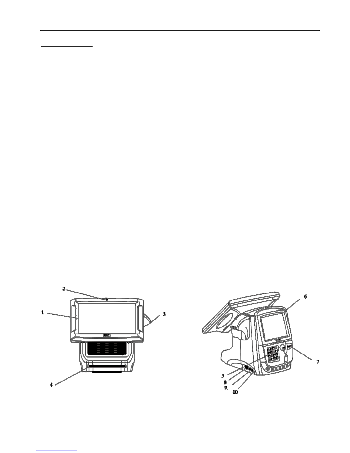
POS REGISTER
Item Description
1. LCD display A screen that shows programming or order information.
2. Power indicator Shows that power is present.
3. Bar Code Reader Scanner for reading bar codes. This is a feature and may not be present
on all registers.
4. Magnetic Card Reader Accepts employee keycards. Provides access to functions. Not present on
all registers.
5. PIN pad PIN pad allowing the use of debit cards. This is a feature and may not be
present on all registers.
6. Customer Display Displays to the customer order total, tax total, and any changes due. It
may also show present advertisement information or messages. This is a
feature and may not be present on all registers.
7. Credit Card Reader Magnetic card reader for credit/debit card transactions. This is a feature
and may not be present on all registers.
8. USB 2.0 ports (Universal serial bus) ports. Used for connecting keyboard or mouse.
9. Microphone Jack Jack to plug in external microphone.
10. Speaker/Headphone Jack Jack to plug in external speaker or headphone.
5
Item Description
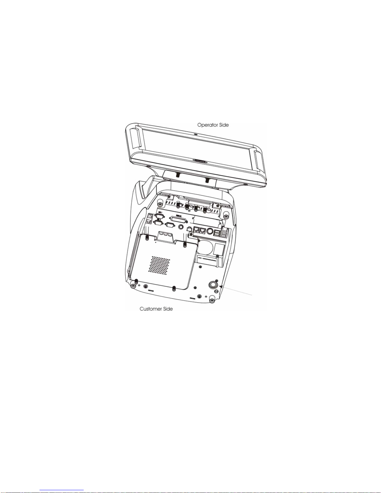
11. Power switch Push in momentarily to turn “on”, push and hold to turn “off”. You can
reach it by sliding your hand under the right side of the register toward
the back. Leave the register on at all times, except when servicing the
unit. If a register is not plugged into an uninterruptible power supply
(UPS), you must turn it off during power failures as well.
11
6
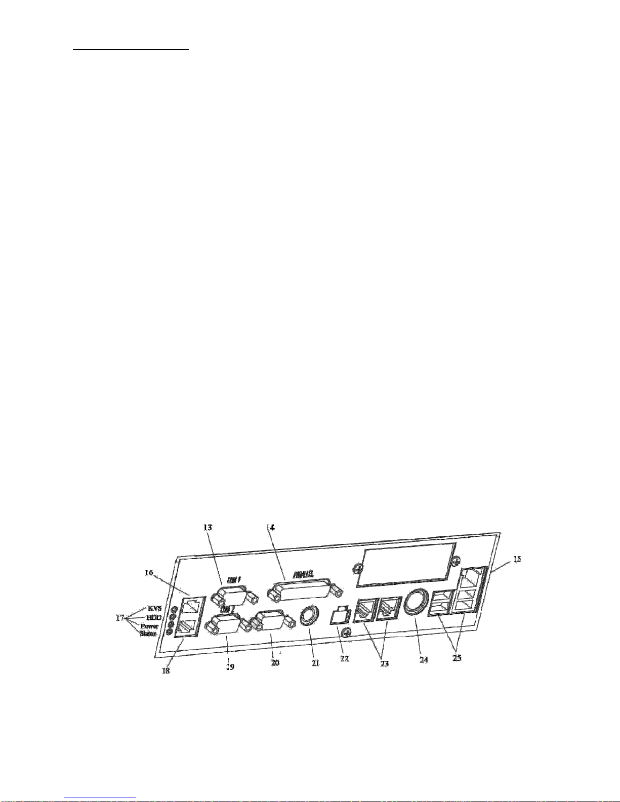
CONNECTOR WELL
Item Description
13. COMM serial port 1 Connects to coin dispensers, remote customer displays, remote order
(RS-232-C) displays, EFT devices, printers, and other serial devices.
14. Printer port Connects to a cable from a printer—A Centronics-compatible.
15. LAN receptacle Connects to a LAN cable.
16. COMM serial port 4 Connects to coin dispensers, remote customer displays, remote order
(RS-232-C) displays, EFT devices, printers, and other serial devices.
17. Status lights Provide troubleshooting information to service personnel. (KVS, HDD,
Power, Status).
18. COMM serial port 7 Connects to coin dispensers, remote customer displays, remote order
(RS-232-C) displays, EFT devices, printers, and other serial devices.
19. COMM serial port 2 Connects to coin dispensers, remote customer displays, remote order
(RS-232-C) displays, EFT devices, printers, and other serial devices.
20. COMM serial port 3 Connects to coin dispensers, remote customer displays, remote order
(RS-232-C) displays, EFT devices, printers, and other serial devices.
21. Keyboard receptacle Allows connection of a PC keyboard (mini DIN).
22. MSR Magnetic strip reader.
23. Cash drawer receptacle Connect to the cables from up to two cash drawers.
24. Remote video receptacle Connects to the cable from the remote video controller.
25. USB connectors (Universal serial bus) Connect to other devices like coin dispensers or
printers.
7

SPECIFICATIONS
ViGo POS Features:
♦Processors
oF6100R – 2.0GHz Celeron Processor w/fan
oF6101R – 2.0GHz Pentium 4 Processor w/fan
oF6102R– 2.5GHz Celeron Processor w/fan
oF6103R – 2.4GHz Pentium 4 Processor w/fan
oF6104R – 2.8GHz Pentium 4 Processor w/fan
♦Memory
oF6201R – 256 MB DDR SDRAM
oF6202R - 512MB DDR SDRAM
oF6203R - 1GB DDR SDRAM
♦Magnetic Strip Readers
oF6300R – Operator 2 Track Mag Strip Reader Swipe
oF6303R – 3-Track Mag Stripe reader (crew side)
oF6320R – Blank Cover Plate (when no MSR ordered)
♦Hard Drive/CD ROM/DVD
oF6400R – 3.5” 10GB Hard Disk Drive
oF6430R – DVD-RW Drive Laptop Style Thin
oF6435R – CD-ROM Drive Ultra Slim
♦PCI Option Cards
oF6500R – 512 KB BB SRAM
oF6550R – Mini-PCI 802.11 G Wireless LAN
ViGo POS Options:
♦F6700R - Stereo Audio/Dual USB
♦F6750R – Powered USB
8

BIOS
Introduction
This user manual describes the AMI BIOS setup program and configuration options of the ViGo
motherboard. The BIOS setup program allows users to modify the basic system configuration.
Starting Setup
The AMI BIOS is activated when the computer is turned on. The setup program can be activated by
pressing the F2 key as soon as the system is turned on.
Using Setup
Use the arrow keys to highlight items, press ENTER to select, use the PageUp and PageDown keys to
change entries, press F1 for help and press ESC to quit. Navigation keys are shown in.
Key Function
Up arrow Move to previous item
Down arrow Move to next item
Left arrow Move to the item on the left hand side
Right arrow Move to the item on the right hand side
Esc key Main Menu – Quit and not save changes into CMOS
Status Page Setup Menu and Option Page Setup Menu -- Exit current
page and return to Main Menu
Page Up key Increase the numeric value or make changes
Page Dn key Decrease the numeric value or make changes
F1 key General help, only for Status Page Setup Menu and Option Page Setup
Menu
F2 /F3 key Change color from total 16 colors. F2 to select color forward.
F10 key Save all the CMOS changes, only for Main Menu
Table 1-1: BIOS Navigation Keys
Getting Help
When F1 is pressed a small help window describing the appropriate keys to use and the possible selections
for the highlighted item appears. To exit the Help Window press ESC or the F1 key again.
Unable to Reboot after Configuration Changes
If the computer cannot boot after changes to the system configuration is made, CMOS defaults. Use the
clear CMOS jumper described in the motherboard user manual.
BIOS Menu Bar
The menu bar on top of the BIOS screen has the following main items:
Main Changes the basic system configuration.
Advanced Changes the advanced system settings.
PCIPnP Changes the advanced PCI/PnP Settings
Boot Changes the system boot configuration.
Chipset Changes the chipset settings.
Power Changes power management settings.
Exit Selects exit options and loads default settings
9
The following sections completely describe the configuration options found in the menu items at the top of
the BIOS screen and listed above.
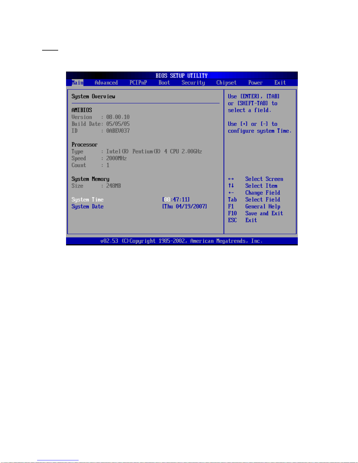
Main
The Main BIOS menu appears when the BIOS Setup program is entered. The Main menu gives an
overview of the basic system information.
BIOS Menu 1: Main
System Overview
The System Overview lists a brief summary of different system components. The fields in System
Overview cannot be changed. The items shown in the system overview include:
AMI BIOS: Displays auto-detected BIOS information
oVersion: Current BIOS version
oBuild Date: Date the current BIOS version was made
oID: Installed BIOS ID
Processor: Displays auto-detected CPU specifications
oType: Names the currently installed processor
oSpeed: Lists the processor speed
oCount: The number of CPUs on the motherboard
System Memory: Displays the auto-detected system memory.
oSize: Lists memory size
The System Overview field also has two user configurable fields:
System Time [xx:xx:xx]
Use the System Time option to set the system time. Manually enter the hours, minutes and seconds.
System Date [xx/xx/xx]
10
Ce manuel convient aux modèles suivants
1
Table des matières
Autres manuels PAR Terminal tactile


Manuels Terminal tactile populaires d'autres marques

Wincor Nixdorf
Wincor Nixdorf iPOS plus Advanced Manuel utilisateur

Ingenico
Ingenico AXIUM EX4000 Manuel utilisateur

Heisei Electronics
Heisei Electronics Q-POS 815 Manuel utilisateur

Amano
Amano MTX-15 Manuel utilisateur

FLOWBIRD
FLOWBIRD CWT Compact Touch Manuel utilisateur

Demco
Demco SP7 Manuel utilisateur


