ooznest Prusa i3 Manuel utilisateur

Prusa i3
Assembly Instructions

Overview
The Prusa i3 is the third iteration in the series of printers designed Josef Prusa. Our kit uses his open-
source design and adds many beneficial upgrades. Our kit includes all the parts required to build a Prusa i3,
plus many extras that ill help you get printing as quickly as possible.
What we have done for you
In our kit, all plastic parts have been pre-prepared and checked for fitting. For plastic parts that require
nuts to be inset, this has been completed. Ho ever, please check the plastic parts box for any that may
have fallen out during shipping. Instruction steps marked ith an '*' means some parts of this step have
already been completed by us.
All ires that need terminal connectors have been pre-crimped and terminals attached. We have not cut
ires to a certain length so you can do the cable management the ay you prefer. Z-Axis motor ires have
been inserted through the holes in the frame.
The MK2B Aluminium heated bed has 1-metre po er ires pre-soldered, and the thermistor is pre-
attached.
The Hexagon Hotend has been assembled ith cartridge heater and thermistor attached. It has been pre-
heated and tightened at 285°C. The Hexagon Hotend has been pre-attached to the Bulldog Lite Extruder.
Arduino Mega2560, RAMPS 1.4 & Stepper drivers (heat sinks still need to be attached) are pre-assembled
and flashed ith pre-configured firm are. The output current on the stepper drivers has also been set.
Notes on assembly
Using Appendix A, check that all parts have been supplied and no parts have been damaged during
shipping. If there are any problems, contact us, and e ill rectify the issue as quickly as possible.
It is recommended to read through the instructions thoroughly before starting assembly.
Ensure you have a clear, firm, and level table to assemble the printer on and you are using tools safely. Also
take extreme caution hen iring electronics.
Most ashers have a flat side and a rounded side. It is recommended to put the flat side against the plastic
part. Take care to not overtighten the nuts & bolts that are in contact ith plastics parts because they may
crack.
If you have any problems contact us (details on our ebsite), and e ill help to resolve the problem.
Most importantly, take your time and have fun!
Tools Re uired
●Allen keys (supplied ith kit)
●5.5/7.0mm Spanners (M3/M4 nuts)
●2 x 13/17mm spanners or 2 x adjustable spanners (M8/M10 nuts)
●Pliers (Preferably Long Nose)
●Mallet or hammer
●Large & small philips scre driver
●Ceramic scre driver (supplied ith kit)
●T eezers
●Scissors
●Ruler
2 of 62

Y-Axis Idler Assembly
Instructions
A)* Insert a M4-Hex-Nut into the inset provided on the backside of the Y-Axis-Idler. Scre a M4-20mm-Bolt
through the M4-Hex-Nut Nut until it is just about to come through the other side of the M4-Hex-Nut.
B) Scre a M3-25mm-Bolt through 2 x 623zz-Flanged Bearings, as in the diagram, ensuring that t o M3-
Washers are included. Attach a M3-Nyloc-Nut, and tighten the M3-25mm-Bolt. Once tight check the
bearing assembly rotates freely.
3 of 62

A) Thread M8-Hex-Nuts, M8-Washers, Y-Axis-Idler & Y-Axis-Corners along the 2 x Threaded-Rods-8mm in
the order as sho n in the diagram.
B) Finger tighten the M8-Hex-Nuts so the Y-Axis-Idler and Y-Axis-Corners are as sho n in the left-hand
image. Make sure the 8mm-Threaded-Rod is touching the backside of the elongated hole on the Y-Axis-
Idler hen tightening the nuts on either side of it. All nuts ill be fully tightened at a later stage.
Instructions
4 of 62
Y-Axis Front Assembly
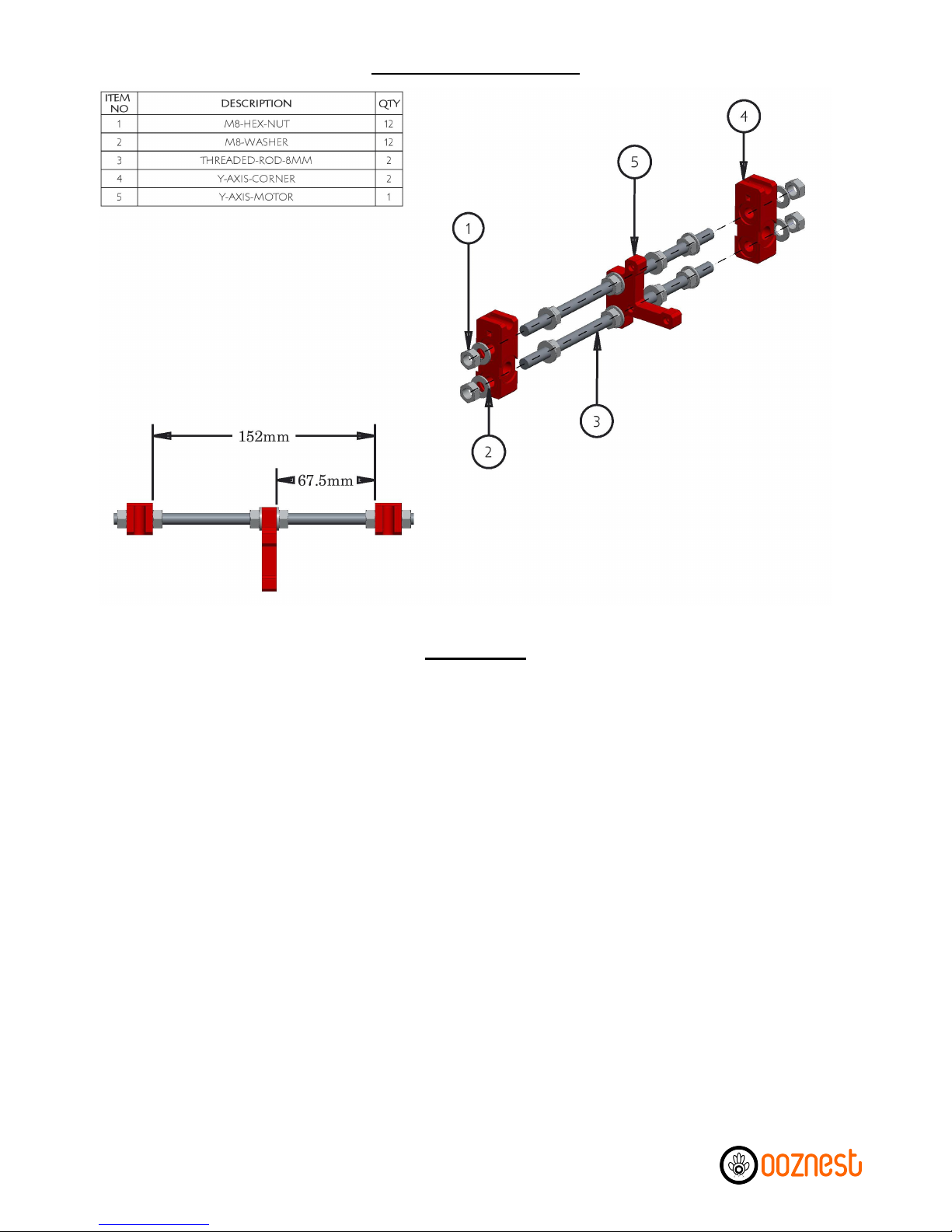
A) Thread M8-Hex-Nuts, M8-Washers, Y-Axis-Motor & Y-Axis-Corners along the 2 x Threaded-Rod-8mm in
the order as sho n in the diagram.
B) Finger tighten the M8-Hex-Nuts so the Y-Axis-Idler and Y-Axis-Corners are as sho n in the left-hand
image. Make sure the Y-Axis-Motor is perpendicular to both Threaded-Rods-8mm hen tightening the
nuts on either side. All nuts ill be fully tightened at a later stage.
Y-Axis Back Assembly
Instructions
5 of 62
Instructions

A)* Insert M3-Nyloc-Nuts into each of the hex insets on the 4 Heated-Bed-Spring-Traps. Push a Heated-
Bed-Spring-Trap onto each corner of the Y-Axis-Bed-Plate
B) Attach the Y-Axis-Belt-Holder to the Y-Axis-Bed-Plate using 2 x M3-16mm-Bolts & 2 x M3-Nyloc-Nuts.
Ensure you place a M3-Washer in bet een each M3-16mm-Bolt head and the Y-Axis-Belt-Holder. Make
sure the Y-Axis-Belt-Holder is straight before fully tightening the bolts.
C) On each Y-Axis-Bearing-Holder insert a cable tie through each of the 2 provided slots so it goes in on the
same side the bearing ill sit on, then the hole ay under the bearing holder and comes back out on the
same side. Do not tie them up.
D) Insert a LM8UU-Bearing into each Y-Axis-Bearing-Holder. Attach each Y-Axis-Bearing-Holder to the
Y-Axis-Bed-Plate using 2 x M3-30mm-Bolts & 2 x M3-Nyloc-Nuts. Make sure they are straight before fully
tightening the bolts. For the 2 x Y-Axis-Bearing-Holders on the left-hand side, it is recommended to
temporarily insert any one of the 8mm-Smooth-Rods through the t o LM8UU-Bearings hile tightening
the bolts to ensure the LM8UU-Bearings are centred on each other.
E) The cable ties previously inserted can no be used to securely attach the LM8UU-Bearings to the Y-Axis-
Bearing-Holders. If available, use pliers to firmly pull the cable ties. The 8mm-Smooth-Rod can no be
removed.
Y-Axis Bed Assembly
6 of 62
Instructions

A) Thread M10-Hex-Nuts, M10-Washers, M10-Penny-Washers, Y-Axis-Front & Y-Axis-Back onto both
Threaded-Rods-10mm in the order as sho n in the diagram.
B) Insert 2 x Smooth-Rods-350mm through the LM8UU-Bearings of the previously assembled Y-Axis-Bed,
and then insert the ends of the Smooth-Rod-350mm into the insets on the Y-Axis-Corners. Make sure the
side on the Y-Axis-Bed ith one LM8UU-Bearing is on the left-hand side of the assembly. Ensure the ends
of the Smooth-Rods-350mm are touching the ends of all 4 insets on the Y-Axis-Corners.
C) Tighten the hole assembly, including the M8-Hex-Nuts on the front and back sides (except from the
M8-Hex-Nuts on either side of the Y-Axis-Idler). All 4 Y-Axis-Corners should be touching the ground. If not,
to diagnose, individually check all 4 Y-Axis-Corners after tightening each bolt, and recheck distances
bet een the Y-Axis-Corners on the front & back sides. Make sure both Smooth-Rods-350mm cannot move
for ard or back ards but can still be lifted out of the insets.
D) Check that the motion of the Y-Axis-Bed is smooth. If not recheck the distances bet een the Y-Axis-
Corners on the front & back sides.
E) The M10-Penny-Washers should be roughly 130.5mm from the back side, as sho n in the right-hand
picture. These ill be tightened against the Z-Axis-Frame later.
F) At this point, do not zip tie do n the Smooth Rods.
Y-Axis Assembly
Instructions
7 of 62
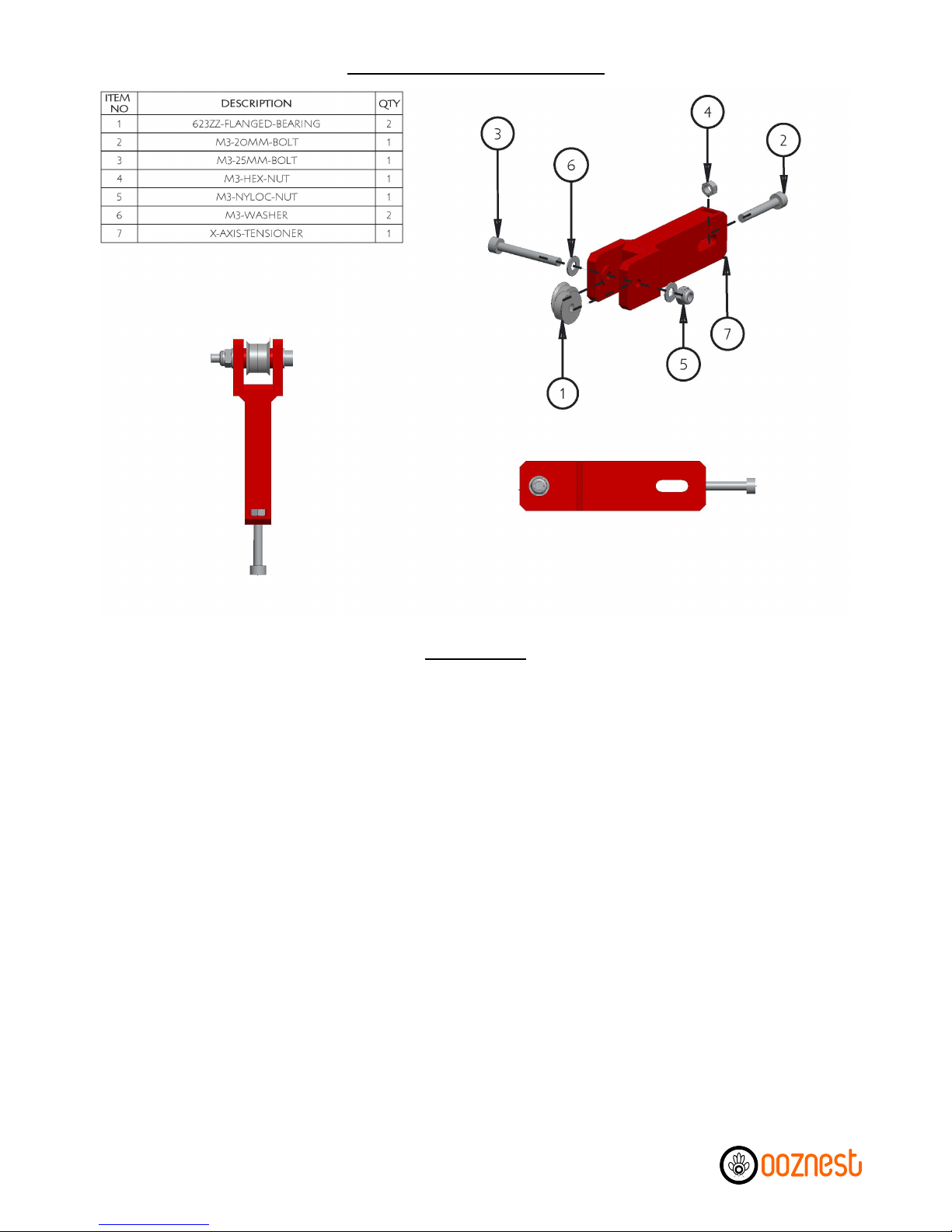
A) Insert A M3-Hex-Nut into the inset provided on the backside of the X-Axis-Tensioner. Scre a M3-
20mm-Bolt through the M3-Hex-Nut until it is just about to come through the other side of the M3-Hex-
Nut.
B) Scre a M3-25mm-Bolt through 2 x 623zz-Flanged-Bearings, as in the diagram, ensuring that t o M3-
Washers are included. Attach a M3-Nyloc-Nut, and tighten the M3-25mm-Bolt. Once tight, check the
bearing assembly rotates freely.
X-Axis Tensioner Assembly
Instructions
8 of 62

A) Insert the X-Axis-Tensioner through the horizontal slot in the X-Axis-Idler, as sho n above. Scre a M4-
25mm-Bolt through the X-Axis-Idler & X-Axis-Tensioner, remembering to include the M4-Washers. Then
attach a M4-Nyloc-Nut and finger tighten. This ill be fully tightened later once the GT2-Belt has been
connected.
B) Push a LM8UU-Bearing into the top & bottom slots of the X-Axis-Idler. Clamp each LM8UU-Bearing in
position using a M3-25mm-Bolt, 2 x M3-Washers & M3-Nyloc-Nut. Before tightening the M3-25mm-Bolts,
insert an 8mm-Smooth-Rod through both LM8UU-Bearings to ensure they are centred on each other.
Make sure the bearings are flush ith the top & bottom surfaces on the X-Axis-Idler. Only slightly tighten
the M3-25mm-Bolts; other ise, the 8mm-Smooth-Rod ill no longer ride smoothly through the LM8UU-
Bearings. The 8mm-Smooth-Rod can no be removed.
X-Axis Idler Assembly
Instructions
9 of 62

A)* Insert a M3-Hex-Nut into the slot provided on the right-hand side of the X-Axis-Motor. Scre a M3-
25mm-Bolt through a M3-Washer & Compression Spring. Once through the other side, attach a M3-Nyloc-
Nut to the end. While holding the M3-Nyloc-Nut ith a spanner, scre the M3-25mm-Bolt until it is flush
ith the bottom of the M3-Nyloc-Nut. The M3-25mm-Bolt ill be adjusted later to trigger the Mechanical-
Endstop.
B) Push a LM8UU-Bearing into the top & bottom slots of the X-Axis-Motor. Clamp each LM8UU-Bearing in
position using a M3-25mm-Bolt, 2 x M3-Washers & M3-Nyloc-Nut. Before tightening the M3-25mm-Bolts,
insert an 8mm-Smooth-Rod through both LM8UU-Bearings to ensure they are centred on each other.
Make sure the bearings are flush ith the top & bottom surfaces on the X-Axis-Motor. Only slightly tighten
the M3-25mm-Bolts; other ise, the 8mm-Smooth-Rod ill no longer ride smoothly through the LM8UU-
Bearings. The 8mm-Smooth-Rod can no be removed.
X-Axis Motor Assembly
Instructions
10 of 62
Autres manuels pour Prusa i3
1
Table des matières
Autres manuels ooznest Imprimante 3D


