NWA3D Afinibot A31 Manuel utilisateur

Afinibot A31 User Manual
1. Assembly
2. Fine-Tuning
3. Leveling the Build Plate
4. Loading and Unloading Filament
5. Operation: The Four Steps of 3D Printing
6. Troubleshooting
7. Additional Resources
© 2017 NWA3D LLC Version 1.1

NWA3D Afinibot A31 User Manual
1. Assembly
1. Remove the parts from the box and remove any tape and padding from the parts.
Inspect the parts to make sure they were not damaged in shipment.
2. Install the gantry frame (A) to the base frame (B).
a. On the gantry frame, make sure the nozzle assembly is to the front, and the
long vertical lead screw is to the back. On the base frame, make sure the
black belt cover is on the front, and the stepper motor is on the back.
b. Use the M5x20 screws (4) and lock washers (4). Raise the base frame above
the table with two blocks (boxes, books, etc.) Install the screws through the
base frame into the threaded holes in the gantry frame. Tighten with the M5
hex key (Allen) wrench.
A B
2
© 2017 NWA3D LLC
NWA3D Afinibot A31 User Manual
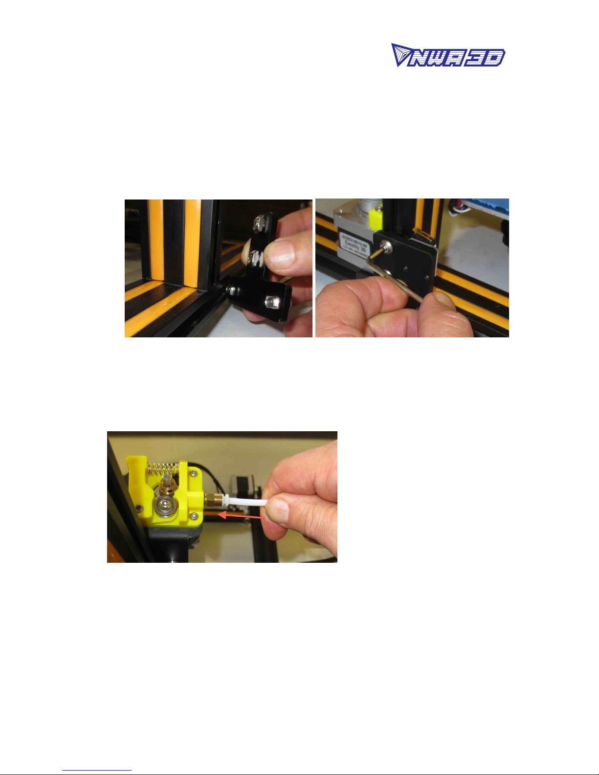
3. Install the two T-shaped frame reinforcement plates. The plate with the limit
switch goes on the left. The plate without the limit switch goes on the right.
a. Loosen the t-nuts by hand and turn them so they will fit inside the grooves on
the frames. You want the nuts to be loose so that when you tighten the bolts,
the nuts will rotate 90° and grab onto the inside of the groove.
b. Align the nuts to the grooves and insert the T-shaped plates into the frames.
c. Tighten all eight bolts using the M4 hex key (Allen) wrench.
4. Attach the white PTFE Bowden tube coming out of the hot end to the yellow tube
coupler on the extruder. Firmly push the tube into the connector on the
extruder. You should feel it slide in and lock into place.
5. Cut and discard the tie wrap holding the nozzle to the gantry frame.
6. Install the filament spool holder.
a. Attach the bracket to the top of the power & control box using two
thumbscrews. Tighten the screws by hand. Do not overtighten.
b. Remove the first nut from the double-nut side of the filament holder tube.
Install the tube into the bracket and re-install the nut to hold it in place.
Tighten the two nuts by hand so that the tube is snugly attached to the
3
© 2017 NWA3D LLC

NWA3D Afinibot A31 User Manual
bracket. Do not overtighten.
c. Tighten the nut on the other end of the tube by hand. Do not overtighten.
7. Connect all electrical cables.
a. Put the power & control box on the left side of the printer with the screen
facing forward.
b. On the right side of the power & control box, make sure the red voltage select
switch reads “110V.” If it doesn’t, select “110V” by gently sliding the switch
with a screwdriver or other tool.
c. Connect the heater cables to the power & control box.
The cable for the build plate heater has four pins. The cable for the nozzle
heater has eight pins. Rotate the connector until the pins slide easily into the
socket. Do not force them. After the pins are fully inserted, hand-tighten the
knurled nuts so they don’t become unplugged.
4
© 2017 NWA3D LLC

NWA3D Afinibot A31 User Manual
d. Connect the stepper motor and limit switch cables.
The Y cables go to the motor and switch at the back of the base frame that
move the build plate. The Z cables go to the motor and switch on the left side
of the base frame that raise and lower the nozzle. The X and E (extruder)
cables go onto the gantry frame. The X cables go to the motor and switch that
runs the belt and the E cable goes to the motor that feeds the filament. Hint:
Install the smaller limit switch connectors first. Small hands are an
advantage. Try not to bend the pin connectors as you push them in.
5
© 2017 NWA3D LLC

NWA3D Afinibot A31 User Manual
e. Connect the power cord to the back of the power & control box and to a
standard 110-volt electrical outlet.
f. Turn the power on using the switch on the back of the power &control box.
g. To operate the controls, rotate the button to scroll and push the button to
select.
6
© 2017 NWA3D LLC

NWA3D Afinibot A31 User Manual
2. Fine-Tuning
1. Adjust the tension of the build plate assembly on the Y-axis on the base frame.
a. Check the tension of the build plate assembly. Hold the build plate carriage
under the build plate and try to wiggle it left and right. If the build plate
assembly wiggles back and forth on the Y-axis track, it is too loose.
b. To tighten the build plate assembly, rotate the three eccentric nuts that
connect the three wheels to the right side of the build plate assembly. Use the
open-end wrench to rotate the nuts slightly—a quarter turn is usually
enough—until each of the three wheels is snug against the Y-axis frame and
the carriage no longer wobbles.
c. Re-check the tension of the build plate assembly. The assembly and the belt
should move forward and backward without much effort, but there should
have no side-to-side wiggle or play.
2. Adjust the tension of the gantry on the right pillar of the gantry frame.
a. Check the tension of the gantry assembly at the right pillar of the frame. Hold
the gantry and try to wiggle it up and down. If the gantry wobbles on the
right pillar frame, it is too loose.
b. To tighten the carrgantryiage, rotate the one eccentric nut that connects the
wheel to the inside of the gantry. Use the open-end wrench to rotate the nut
slightly—a quarter turn is usually enough—until the wheel is snug against
the frame pillar and the gantry no longer wobbles.
7
© 2017 NWA3D LLC

NWA3D Afinibot A31 User Manual
3. Adjust the tension of the nozzle assembly on the X-axis on the gantry frame.
a. Check the tension of the nozzle assembly. Hold the mounting bracket behind
the nozzle and try to wiggle it back and forth. If the nozzle assembly wobbles
on the X-axis track, it is too loose.
b. To tighten the nozzle assembly, rotate the one eccentric nut that connects the
wheel to the bottom of the nozzle assembly. Use the open-end wrench to
rotate the nut slightly—a quarter turn is usually enough—until the wheel is
snug against the X-axis frame and the assembly no longer wobbles.
c. Re-check the tension of the nozzle assembly. The assembly and the belt
should move left and right without much effort, but there should have no
side-to-side wiggle or play.
8
© 2017 NWA3D LLC

NWA3D Afinibot A31 User Manual
4. Check the tension of the belt driving the Y-axis (under the build plate). The belt
should be taut, with no slack or slop.
a. If the belt is loose:
Loosen the four bolts at the front of the base frame holding the belt follower
pulley to the base frame.
Using an Allen wrench as a lever, push the follower pulley to tighten the belt.
Holding the belt taut, tighten the four bolts.
5. Check the tension of the belt driving the X-axis (on the gantry). The belt should
be taut, with no slack or slop.
a. If the belt is loose:
Loosen the two bolts at the right side of the gantry holding the belt follower
pulley to the gantry.
Using an Allen wrench as a lever, push the follower pulley to tighten the belt.
Holding the belt taut, tighten the two bolts.
9
© 2017 NWA3D LLC

NWA3D Afinibot A31 User Manual
10
© 2017 NWA3D LLC
Autres manuels pour Afinibot A31
3
Table des matières
Autres manuels NWA3D Imprimante 3D


