
IEF Werner easyLINE Manuel utilisateur

October 2019 Mounting instructions
MAN_EN_1040582_easyLINE_R3b.doc easyLINE Page 1 of 34
IEF-Werner GmbH
Wendelhofstraße 6
78120 Furtwangen - Germany
Phone: +49 7723-925-0
Fax: +49 7723-925-100
www.ief.de
info@ief-werner.de
Mounting instructions (Translation)
Module easyLINE
Issue: October 2019
Article no.: 1040582

Mounting instructions October 2019
Page 2 of 34 easyLINE MAN_EN_1040582_easyLINE_R3b.doc
Change History:
Trademarks and trade names are used without any warranty of their free usability. Texts and examples
were created with great care. Nevertheless, errors cannot be excluded. IEF-Werner GmbH does not
assume legal responsibility nor any liability for missing or incorrect statements and their consequences.
IEF-Werner GmbH reserves the right to modify or improve the software or hardware or parts of it, as
well as the supplied documentation or parts of it, without previous notice.
IEF-Werner GmbH expressly reserves all rights for replication and photomechanical reproduction,
including in extracts.
We are always grateful for suggestions for improvements and information about errors.
© October 2019, IEF-Werner GmbH
Document Code Date Revision
MAN_EN_1040582_easyLINE_R2b.doc 26.02.2007 Release of the English Document (“MAN_EN_
1040582_easyLINE_R2b.doc”).
MAN_EN_1040582_easyLINE_R3a.doc 13.06.2013
Document updated regarding the new machinery directive
(MRL 2006/42/EC).
Made from German document
“MAN_DE_1040581_easyLINE_R3a.doc”.
MAN_EN_1040582_easyLINE_R3b.doc 21.10.2019 Standards updated in the Declaration of incorporation.

October 2019 Mounting instructions
MAN_EN_1040582_easyLINE_R3b.doc easyLINE Page 3 of 34
Table of Contents
1Safety 5
1.1 Definition or warning notes 5
1.2 General warning notes 5
1.3 Special hazard warnings 6
2Intended use 7
2.1 Reasonably foreseeable misuse 7
3Assembly instructions 8
3.1 Installation position 8
3.2 Overview of motor installation variants 8
3.2.1 Installation variant 1 9
3.2.2 Installation variant 5 9
3.3 Attachment 10
3.3.1 Mounting with clamping elements 10
3.3.2 Attachment at the carriage of the linear module 12
3.3.3 Installation of actuators 13
3.4 Wiring 14
3.4.1 Motors 14
3.4.2 Initiators 14
3.4.2.1 Plug end position switch 16
3.4.3 Cable routing 16
3.5 Technical data 17
3.5.1 Tightening torques for screw connections 17
3.5.2 Technical Data of easyLINE module 17
3.5.4 Technical data when using a planetary gear 18
3.5.5 Load cases 19
3.5.5.1 Torques and load carrying capacity 19
4Maintenance 20
5Trouble shooting 21
6Repair instructions 23
6.1 Toothed belt tension 23
6.2 Belt tension gear toothed belt 23
7Parts lists and drawings 24

Mounting instructions October 2019
Page 4 of 34 easyLINE MAN_EN_1040582_easyLINE_R3b.doc
7.1 easyLINE installation variant 1 24
7.2 Reversing unit easyLINE (Article.No. 526261) 26
7.3 Carriage easyLINE completed (Article no. 526311) 27
7.4 Long carriage easyLINE complete (Article no. 526609) 28
7.5 Gearbox (Subassembly no. 1000002) 29
7.6 Flange i = 1:1 (Subassamly no. 1000003) 30
7.7 easyLINE clamping block complete – exploded view (Article no. 526262) 31
7.8 easyLINE long carriage clamping block complete - exploded view (Article no.
526610) 32
7.9 easyLINE, parallel drive – exploded view 33
8Declaration of incorporation 34
October 2019 Mounting instructions Safety
MAN_EN_1040582_easyLINE_R3b.doc easyLINE Page 5 of 34
1 Safety
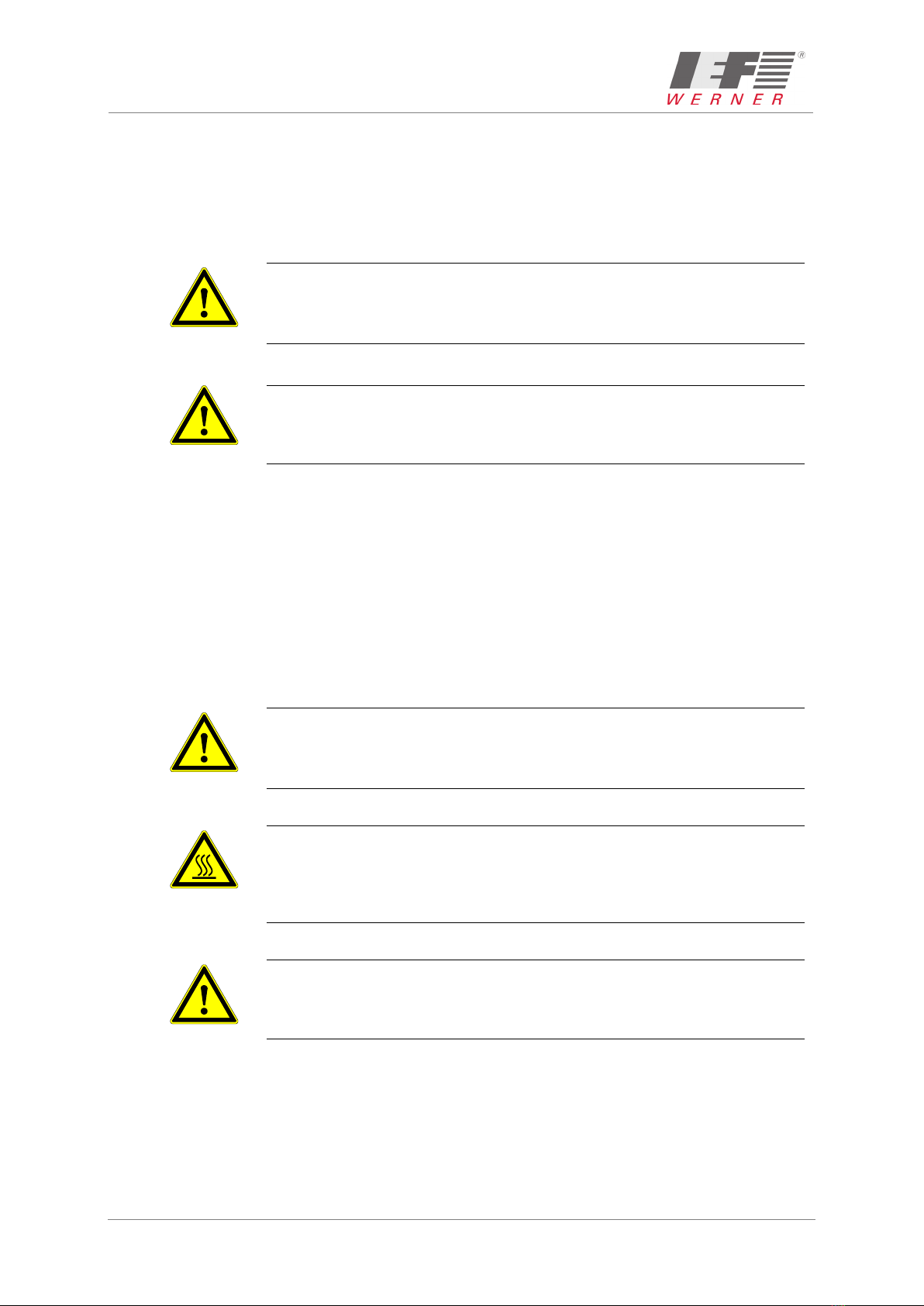
1.1 Definition or warning notes
WARNING
Indicates potential danger. Non-observance of the safety provisions
may cause death or severe injury.
CAUTION
Indicates potential danger. Non-observance of the safety provisions may
cause property damage or injury.
NOTE Offers additional information.
1.2 General warning notes
The module must only be commissioned by specialists who received safety-technical
instruction and are able to assess potential dangers. Furthermore, all chapters of these
operating instructions must have been read and understood completely.
WARNING
The system must be powered down for all assembly, disassembly or
repair work. There is a high danger of injury.
WARNING OF HOT SURFACE
During operation, heating of the motor, in particular of stepper motors, can
cause burns of the skin when touching the motor. Install a protective device, if
possible! Do not touch the marked areas or wait for an adequate cooling time.
CAUTION
Motor connectors must not be inserted or disconnected when live. Risk of
burning of the contacts and risk of flying sparks.

Safety Mounting instructions October 2019
Page 6 of 34 easyLINE MAN_EN_1040582_easyLINE_R3b.doc
CAUTION
Linear modules always have to be operated in connection with suitable safety
devices (e.g., safety cell, protective room, protective housing, light curtain).
NOTE Observe the Manufacturer's Declaration (see section Declaration of
incorporation, page 34).
1.3 Special hazard warnings
In addition, this operating instructions also contains the following special hazard warning:
DANGER FROM CRUSHING
These places of the components pose the danger of crushing limbs in
operation.

October 2019 Mounting instructions Intended use
MAN_EN_1040582_easyLINE_R3b.doc easyLINE Page 7 of 34
2 Intended use
The easyLINE module (see Figure 1) is a precise, linear adjustment unit with toothed belt drive
that is used in the commercial area as an attachment part in connection with other
components. In combination with many standardised installation elements and the other linear
modules of IEF-Werner GmbH (e.g. module 68 and 68D, module 105, module 105 S, module
142 and module 142 S), complex multi-axis handling systems can be developed as well.
Figure 1: easyLINE module
The areas of application of an easyLINE module are accordingly diverse.
They encompass:
■Stop adjustment in the wood industry
■Equipment systems for SMD components
■Joining and press-in processes in precision mechanics
■Loading and unloading station of tool machines up to
■Manipulators for the packaging industry
2.1 Reasonably foreseeable misuse
The easyLINE module is not to be used for certain applications, and in particular not for such
as the transport of persons and animals or as a pressing/bending device for cold working of
metal.
Use of the linear module without additional measures is also notpossible in special fields of
application, such as the chemical or food industry or in explosive atmospheres.
In case of doubt, consult the manufacturer.

Assembly instructions Mounting instructions October 2019
Page 8 of 34 easyLINE MAN_EN_1040582_easyLINE_R3b.doc
3 Assembly instructions
3.1 Installation position
The installation position is optional, i.e. the easyLINE module can be used horizontally as well
as vertically.
CAUTION
In the vertical installation position, use only motors with spring-operated brake
to prevent the lowering of the drive in de-energized condition!
3.2 Overview of motor installation variants
The generally variants of installation are (see Figure 2):
Figure 2: Installation variants easyLINE module
Installation variant 5
Installation variant 1

October 2019 Mounting instructions Assembly instructions
MAN_EN_1040582_easyLINE_R3b.doc easyLINE Page 9 of 34
3.2.1 Installation variant 1
A, B: stroke limited switch
A: standard reference point
AB
M6; 12 deep (4x)
DIN74; Km5 (2x)
DIN 74; Km5 (4x)
M6x12 (10x)
option: easyLINE long carriage
89 (mounting proportion)
65
68 112
stroke-eff. + 105
92
177,2
stroke-eff. + 285
105
89
92
112
92
194
82
105
8
52,5
97
141,5
186
89
Figure 3: easyLINE installation variant 1
3.2.2 Installation variant 5
A, B: stroke limited switch
A: standard reference point
AB
M6; 12 deep (4x)
DIN74; Km5 (2x)
DIN 74; Km5 (4x)
M6;12 deep (10x)
option: easyLINE long carriage
89 (mounting proportion)
65
68
112
stroke-eff. + 105
stroke-eff. + 285
103,5
105
89
92
112
92
194
82
105
8
52,5
97
141,5
186
89
Figure 4: easyLINE installation variant 5

Assembly instructions Mounting instructions October 2019
Page 10 of 34 easyLINE MAN_EN_1040582_easyLINE_R3b.doc
3.3 Attachment
3.3.1 Mounting with clamping elements
The use of clamping elements (see Figure 6) allows the linear unit easyLINE to be easily
secured to a level mounting surface. Standard length clamping elements are available for the
cross-mounting of linear units. For safety reasons, continuous clamping sections are advised.
This ensures hazardous shear points are avoided.
Please avoid additional drilling holes in the basic body. This might damage the internal parts of
the linear unit and could distort the guide base.
CAUTION
The clamping area should have a planeness of 0.1 mm/m²
89
Figure 5: Attachment with clamping elements
Figure 6: Dimensions clamping element
Clamping element Clamping element
Bore distance
Table des matières
Autres manuels IEF Werner Unité de contrôle


Manuels Unité de contrôle populaires d'autres marques

Festo
Festo Compact Performance CP-FB6-E Manuel de la liste des pièces

Elo TouchSystems
Elo TouchSystems DMS-SA19P-EXTME Manuel utilisateur

JS Automation
JS Automation MPC3034A Manuel utilisateur

JAUDT
JAUDT SW GII 6406 Series Guide rapide

Spektrum
Spektrum Air Module System Manuel utilisateur

BOC Edwards
BOC Edwards Q Series Manuel utilisateur


