HP Irvine Manuel utilisateur

Irvine Motherboard
User’s Manual

Statement:
This manual is the intellectual property of HP, Inc. Although the
information in this manual may be changed or modied at any time,
Foxconn does not obligate itself to inform the user of these changes.
Trademark:
All trademarks are the property of their respective owners.
Version:
User's Manual V1.0 for Irvine motherboard.
Symbol description:
Caution : refers to important information that can help you to use
motherboard better, and tells you how to avoid problems.
Warning: indicating a potential risk of hardware damage or physical
injury may exist.
WEEE: The use of this symbol indicates that this product may not
be treated as household waste. By ensuring this product is
disposed of correctly, you will help prevent potential negative
consequences for the environment and human health, which
could otherwise be caused by inappropriate waste handling
of this product. For more detailed information about recycling
of this product, please contact your local city ofce, your
household waste disposal service or the shop where you
purchased this product.
W
A
R
N
I
N
G
!
CAUTION
!
© All rights reserved.
All trade names are registered trademarks of respective manufacturers listed.
All images are for reference only, please refer to the physical motherboard for specic features.

Table of ConTenTs
Chapter 1 Product Introduction
Product Specications................................................................ 2
Layout......................................................................................... 4
Back Panel Connectors.............................................................. 5
Chapter 2 Hardware Install
Install the CPU ........................................................................... 7
Install the Memory ...................................................................... 9
Install an Expansion Card..........................................................11
Install other Internal Connectors .............................................. 12
Jumpers.................................................................................... 14
Chapter 3 BIOS Setup
Enter BIOS Setup..................................................................... 17
Main Menu................................................................................ 18
Advanced Menu ....................................................................... 19
Power Menu ............................................................................. 21
Boot Menu ................................................................................ 22
Exit Menu.................................................................................. 24

Installation Precautions
■ Electrostatic discharge (ESD) is the sudden and momentary electric
current that ows between two objects at different electrical potentials.
Normally it comes out as a spark which will quickly damage your electron-
ic equipment. Please wear an electrostatic discharge (ESD) wrist strap
when handling components such as a motherboard, CPU or memory.
■ Ensure that the DC power supply is turned off before installing or
removing CPU, memory, expansion cards or other peripherals. It is
recommended to unplug the AC power cord from the power supply outlet.
Failure to unplug the power supply cord may result in serious damage to
your system.
Please carefully read the following procedures to install your computer :
■ It is suggested to select high-quality, certied fans in order to avoid
damage to the motherboard and CPU due to high temperature. Never
turn on the computer if the CPU fan is not properly installed.
■ We cannot guarantee that your system can operate normally when
your CPU is over-clocked. Normal operation depends on the over-clock
capacity of your device.
■ When connecting hardware components to the internal connectors on the
motherboard, make sure they are connected tightly and securely.
■ When handling the motherboard, avoid touching any metal leads or
connectors.
■ Before turning on the power, please make sure the power supply A/C
input voltage setting has been congured to the local standard.
■ To prevent damage to the motherboard, do not allow screws to come
in contact with the motherboard circuit or its components. Also, make
sure there are no leftover screws or metal components placed on the
motherboard or within the computer casing.
■ If you are uncertain about any installation steps or have a problem related
to the use of the product, please consult a certied computer technician.
W
A
R
N
I
N
G
!
CAUTION
!

Thank you for buying HP’s Irvine motherboard. This motherboard
is one of our new products, and offers superior performance,
reliability and quality, at a reasonable price. This motherboard
adopts the advanced NVIDIA GeForce 7100 / nForce 630i
chipset, providing users a computer platform with a high
integration-compatibility-performance price ratio.
This chapter includes the following information:
■ Product Specications
■ Layout
■ Back Panel Connectors

2
1-1 Product Specications
CPU Support for Intel®CoreTM 2 Duo E6x50, E6x20, E6x00, E4x00 (Conroe)
processors / Intel®Pentium®Dual Core E2xx0 (Conroe1M) processor /
Intel®Celeron®4xx (Conroe-L) processor in the LGA 775 package
Support for Intel® Hyper-Threading Technology
Front Side Bus 1333/1066/800 MHz (FSB)
Chipset NVIDIA GeForce 7100 / nForce 630i
Memory 2 x 240-pin DDR2 DIMM sockets
Support up to 4GB of system memory
Single channel DDR2 800/667/533MHz architecture
Onboard Graphics Integrated in the GeForce 7100 / nForce 630i Chipset
Audio Realtek ALC888S-GR codec
High Denition Audio
2/4/5.1-channel
Support for S/PDIF Out
Support Jack-Sensing function
LAN RTL 8201 10/100Mb/s Ethernet PHY
Expansion Slots 1 x PCI Express x16 slot
1 x PCI Express x1 slot
Onboard Serial ATA II 2 x SATA II connectors
300MB/s data transfer rate
Support hot plug and NCQ (Native Command Queuing )
USB Support hot plug
Support up to 10 USB 2.0 ports (4 rear panel ports, 3 onboard USB
headers providing 6 extra ports)
Supports USB 2.0 protocol up to 480Mb/s
Internal Connectors 1 x 24-pin ATX main power connector
2 x SATA connectors
3 x USB 2.0 headers (supporting 6 x USB devices)
1 x CPU fan header (4-pin)
1 x Front panel header
1 x Front audio header
1 x S/PDIF_OUT header
Back Panel 1 x PS/2 keyboard port
Connectors 1 x PS/2 mouse port
1 x Coaxial S/PDIF Out connector
1 x VGA port
4 x USB 2.0/1.1 ports
1 x RJ-45 port
1 x 1394a port
1 x DVI port
6 x audio jacks (Center/Subwoofer Speaker Out/Rear Speaker Out/Side
Speaker Out/Line In/Line Out/Microphone)

3
Hardware Monitor CPU temperature detection
CPU fan speed detection
CPU fan speed control
Onboard 1394a Support hot plug
400 Mb/s transmission rate
Support 1 independent 1394 unit synchronously
PCI Express x1 Support 250MB/s (500MB/s concurrent) bandwidth
Low power consumption and power management features
PCI Express x16 Support 4GB/s (8GB/s concurrent) bandwidth
Low power consumption and power management features
Green Function Support ACPI (Advanced Conguration and Power Interface)
Support S0 (normal), S1 (power on suspend), S3 (suspend to RAM), S4
(Suspend to disk), and S5 (soft - off)
Operating System Support for Microsoft®Windows® Vista 32 bit and 64 bit/Linux/Free Dos
Form Factor Mini ITX Form Factor, 193mm x 173mm

4
12
14
78
9
10
11
13
6
1
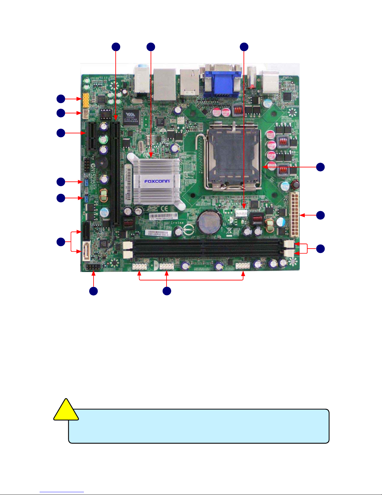
1. Front Audio Connector
2. SPDIF_OUT2 header
3. PCI Express x1 Slot
4. Clear CMOS Jumper
5. CLR_PSWD1 Jumper
6. SATA II Connectors
7. Front Panel Connector
8. Front USB Connectors
1-2 Layout
2
3
4
5
8. Front USB Connectors
9. DDR2 DIMM Slots
10. 24-pin ATX Power Connector : PWR1
11. LGA 775 CPU Socket
12. CPU_Fan Connector
13. Chipset: NVIDIA GeForce 7100 /
nForce 630i
14. PCI Express x16 Slot
The above motherboard layout is provided for reference only;
please refer to the physical motherboard.
CAUTION
!

5
1-3 Back Panel Connectors
1. PS/2 Mouse Port
Use the upper port (green) to connect a PS/2 mouse
2. PS/2 Keyboard Port
Use the lower port (purple) to connect a PS/2 keyboard.
3. Coaxial S/PDIF Out Connector
This connector provides digital audio out to an external audio system that supports
digital coaxial audio. Before using this feature, ensure that your audio system
provides a coaxial digital audio in connector.
4. DVI Port
DVI stands for Digital Visual Interface, and is a standard for connecting computers
to digital monitors. The DVI port provides a pure digital video signal to a digital at-
panel display or projector.
5. USB Port
The USB port supports the USB 2.0/1.1 specication. Use this port for USB devices
such as an USB keyboard/mouse, USB printer, USB ash drive and etc.
6. Line in, Line out, Mic In Jacks
Line In Jack (Blue)
The default line in jack. Use this jack to connect with line out port from devices
such as an Audio CD player, PC line out...etc.
Line Out Jack (Green)
The default line out jack. Use this audio jack for a headphone or 2-channel
speaker.
Mic In Jack (Pink)
The default Mic in jack. Microphone must be connected to this jack.
7. RJ-45 LAN Port
The LAN port provides Internet connection at up to 10/100Mb/s data rate.
8. 1394a Port
Use this port to connect with your 1394a supported video recorder device or any
1394 peripheral.
9.VGA Port
Use this port to to connect with your display monitor.
DVI Port
VGA Port
USB 2.0 Ports
LAN Port
S/PDIF
Coax Port
PS/2
Keyboard Port
PS/2 Mouse Port
Line-out
Microphone
Line-in
5
7
9
1
23 4
1394a Port
8
6

This chapter introduces the hardware installation process,
including the installation of the CPU, memory, power supply,
slots, and pin headers, and the mounting of jumpers. Caution
should be exercised during the installation of these modules.
Please refer to the motherboard layout prior to any installation
and read the contents in this chapter carefully.
This chapter includes the following information:
■ Install the CPU
■ Install the Memory
■ Install an Expansion Card
■ Install other Internal Connectors
■ Jumpers
Table des matières
Autres manuels HP Carte mère

HP
HP MS-6579 Manuel utilisateur

HP
HP A4500A - VMEbus Single Board Computer 744... Manuel utilisateur

HP
HP 744 Instructions d'utilisation

HP
HP MS-6579 Manuel utilisateur

HP
HP XP-P4IM533GV Manuel utilisateur

HP
HP KZM-6120 Manuel utilisateur

HP
HP 59501B Manuel de service

HP
HP MS-6575 Manuel utilisateur

HP
HP Bermuda Manuel utilisateur

HP
HP Compaq 370 Manuel utilisateur
Manuels Carte mère populaires d'autres marques

Telit Wireless Solutions
Telit Wireless Solutions SL869-3DR Manuel utilisateur

Gigabyte
Gigabyte GA-9IVDT Manuel utilisateur

Texas Instruments
Texas Instruments ADS8372EVM Manuel utilisateur

Commell
Commell MS-C73 Manuel utilisateur

IBT Technologies
IBT Technologies MB860 Manuel utilisateur

Nvidia
Nvidia TEGRA DG-04927-001_V01 Manuel utilisateur