HART L20222 Manuel utilisateur

Operating Instructions
L20222
Temperature transmitter
with HART® protocol
BA02278O/09/EN/01.22-00
71600050
2022-11-16
Valid as of version
01.01 (device version)


L20222 Table of contents
3
Table of contents
1 About this document ................ 4
1.1 Document function ..................... 4
1.2 Safety instructions ...................... 4
1.3 Symbols used .......................... 4
1.4 Tool symbols .......................... 5
1.5 Registered trademarks ................... 6
2 Basic safety instructions ............ 7
2.1 Requirements for the personnel ............ 7
2.2 Intended use .......................... 7
2.3 Operational safety ...................... 7
3 Incoming acceptance and product
identification ....................... 8
3.1 Incoming acceptance .................... 8
3.2 Nameplate ............................ 8
3.3 Name and address of manufacturer ......... 9
3.4 Scope of delivery ....................... 9
3.5 Certificates and approvals ................ 9
3.6 Storage and transport .................. 10
4 Mounting ......................... 11
4.1 Mounting requirements ................. 11
4.2 Mounting the device ................... 11
4.3 Post-installation check .................. 16
5 Electrical connection .............. 17
5.1 Connecting requirements ................ 17
5.2 Quick wiring guide ..................... 18
5.3 Connecting the sensor cables ............. 18
5.4 Connecting the transmitter .............. 19
5.5 Special connection instructions ............ 20
5.6 Ensuring the degree of protection .......... 21
5.7 Post-connection check .................. 21
6 Operation options ................. 22
6.1 Overview of operation options ............ 22
6.2 Structure and function of the operating
menu .............................. 25
6.3 Access to the operating menu via the PC
operating tool ........................ 27
6.4 Access to the operating menu via the
Wireless Field Device Configurator App ..... 28
7 System integration ................ 29
7.1 Overview of device description files ......... 29
7.2 Measured variables via HART protocol ...... 29
7.3 Supported HART® commands ............. 29
8 Commissioning .................... 32
8.1 Post-installation check .................. 32
8.2 Switching on the transmitter ............. 32
8.3 Protecting settings from unauthorized access .32
9 Diagnostics and troubleshooting ... 34
9.1 General troubleshooting ................. 34
9.2 Diagnostic information on local display ...... 36
9.3 Diagnostic information via communication
interface ............................ 36
9.4 Diagnostic list ........................ 37
9.5 Event logbook ........................ 37
9.6 Overview of diagnostic events ............. 37
10 Maintenance ...................... 39
11 Repair ............................ 39
11.1 General information ................... 39
11.2 Spare parts .......................... 40
11.3 Return .............................. 40
11.4 Disposal ............................ 40
12 Accessories ....................... 40
13 Technical data .................... 41
13.1 Input ............................... 41
13.2 Output ............................. 42
13.3 Power supply ......................... 43
13.4 Performance characteristics .............. 44
13.5 Environment ......................... 51
13.6 Mechanical construction ................ 52
13.7 Certificates and approvals ............... 54
14 Operating menu and parameter
description ........................ 56
14.1 Menu: Diagnostics ..................... 60
14.2 Menu: Application ..................... 66
14.3 Menu: System ........................ 76
Index .................................. 92

About this document L20222
4
1 About this document
1.1 Document function
These Operating Instructions contain all the information required in the various life cycle
phases of the device: from product identification, incoming acceptance and storage, to
installation, connection, operation and commissioning, through to troubleshooting,
maintenance and disposal.
1.2 Safety instructions
When using in hazardous areas, compliance with national regulations is mandatory.
Separate Ex-specific documentation is provided for measuring systems that are used in
hazardous areas. This documentation is an integral part of these Operating Instructions.
The installation specifications, connection data and safety instructions it contains must be
strictly observed! Make sure that you use the right Ex-specific documentation for the right
device with approval for use in hazardous areas!
1.3 Symbols used
1.3.1 Safety symbols
DANGER
This symbol alerts you to a dangerous situation. Failure to avoid this situation will result in
serious or fatal injury.
WARNING
This symbol alerts you to a dangerous situation. Failure to avoid this situation can result in
serious or fatal injury.
CAUTION
This symbol alerts you to a dangerous situation. Failure to avoid this situation can result in
minor or medium injury.
NOTICE
This symbol contains information on procedures and other facts which do not result in
personal injury.
1.3.2 Electrical symbols
Symbol Meaning
Direct current
Alternating current
Direct current and alternating current
Ground connection
A grounded terminal which, as far as the operator is concerned, is grounded via a
grounding system.
Potential equalization connection (PE: protective earth)
Ground terminals that must be connected to ground prior to establishing any other
connections.
The ground terminals are located on the interior and exterior of the device:
• Interior ground terminal: potential equalization is connected to the supply network.
• Exterior ground terminal: device is connected to the plant grounding system.
L20222 About this document
5
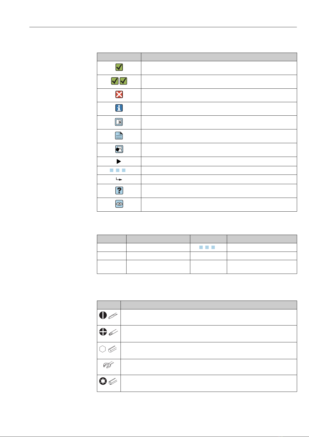
1.3.3 Symbols for certain types of information
Symbol Meaning
Permitted
Procedures, processes or actions that are permitted.
Preferred
Procedures, processes or actions that are preferred.
Forbidden
Procedures, processes or actions that are forbidden.
Tip
Indicates additional information.
Reference to documentation
A
Reference to page
Reference to graphic
Notice or individual step to be observed
1.
,
2.
,
3.
… Series of steps
Result of a step
Help in the event of a problem
Visual inspection
1.3.4 Symbols in graphics
Symbol Meaning Symbol Meaning
1, 2, 3,... Item numbers
1.
,
2.
,
3.
… Series of steps
A, B, C, ... Views A-A, B-B, C-C, ... Sections
-
Hazardous area
.
Safe area (non-hazardous area)
1.4 Tool symbols
Symbol Meaning
A0011220
Flat-blade screwdriver
A0011219
Phillips head screwdriver
A0011221
Allen key
A0011222
Open-ended wrench
A0013442
Torx screwdriver

About this document L20222
6
1.5 Registered trademarks
Bluetooth®
The Bluetooth® word mark and logos are registered trademarks owned by Bluetooth SIG,
Inc. and any use of such marks is under license. Other trademarks and trade names are
those of their respective owners.
HART®
Registered trademark of the FieldComm Group, Austin, Texas, USA

L20222 Basic safety instructions
7
2 Basic safety instructions
2.1 Requirements for the personnel
The personnel for installation, commissioning, diagnostics and maintenance must fulfill
the following requirements:
‣Trained, qualified specialists: must have a relevant qualification for this specific
function and task
‣Are authorized by the plant owner/operator
‣Are familiar with federal/national regulations
‣They must have read and understood the instructions in the manual, supplementary
documentation and certificates (depending on the application) prior to starting work
‣Follow instructions and comply with basic conditions
The operating personnel must fulfill the following requirements:
‣Must be suitably trained and authorized by the plant operator to meet the
requirements of the task
‣Follow the instructions in this manual
2.2 Intended use
The device is a universal and user-configurable temperature transmitter with one sensor
input for resistance thermometers (RTD), thermocouples (TC), resistance and voltage
transmitters. The head transmitter version of the device is intended for mounting in a
terminal head (flat face) as per DIN EN 50446. It is also possible to mount the device on a
DIN rail using the optional DIN rail clip. The device is also optionally available in a version
suitable for DIN rail mounting as per IEC 60715 (TH35).
If the device is used in a manner not specified by the manufacturer, the protection
provided by the device may be impaired.
The manufacturer is not liable for damage caused by improper or non-intended use.
2.3 Operational safety
‣Operate the device only if it is in proper technical condition, free from errors and faults.
‣The operator is responsible for the interference-free operation of the device.
Hazardous area
To eliminate a danger for persons or for the facility when the device is used in the
hazardous area (e.g. explosion protection or safety equipment):
‣Based on the technical data on the nameplate, check whether the ordered device is
permitted for the intended use in the hazardous area. The nameplate can be found on
the side of the transmitter housing.
‣Observe the specifications in the separate supplementary documentation that is an
integral part of these instructions.
Electromagnetic compatibility
The measuring system complies with the general safety requirements as per EN 61010-1,
the EMC requirements as per the IEC/EN 61326 series and the NAMUR recommendations
NE 21.
NOTICE
‣The device must only be powered by a power unit that operates using an energy-limited
electric circuit according to UL/EN/IEC 61010-1, Section 9.4 and the requirements in
Table 18.

Incoming acceptance and product identification L20222
8
3 Incoming acceptance and product
identification
3.1 Incoming acceptance
1. Unpack the temperature transmitter carefully. Is the packaging or content free from
damage?
Damaged components must not be installed as the manufacturer can otherwise
not guarantee compliance with the original safety requirements or the material
resistance, and can therefore not be held responsible for any resulting damage.
2. Is the delivery complete or is anything missing? Check the scope of delivery against
your order.
3. Does the nameplate match the ordering information on the delivery note?
4. Are the technical documentation and all other necessary documents provided? If
applicable: are the Safety Instructions (e.g. XA) for hazardous areas provided?
3.2 Nameplate
The right device?
Compare and check the data on the nameplate of the device against the requirements of
the measuring point:
11-42V 012345678910
xx.yy.zz
Made in Germany 202x, Endress+Hauser Wetzer D-47484 Nesselwang
Ser.no.:
FW:
Input:
Dev.Rev: x
Ext. ord. cd.:
XXXXXXXXXXXXX#
12
4
3
Universal Temperature
Transmitter HART
6
5
A0051223
1 Nameplate of the head transmitter (example)
1 Power supply, current consumption, serial number, device revision and hardware version
2 Radio approval (Bluetooth) and serial number
3 Approvals with symbols
4 Approval data and order code
5 Device name
6 Characters for tag name (TAG)

L20222 Incoming acceptance and product identification
9
2
Universal Temperature
Transmitter HART
Made in Germany 202x, Endress+Hauser Wetzer D-47484 Nesselwang
3
45
6
1
7
A0051224
2 Nameplate of DIN rail transmitter (example)
1 Device name
2 Characters for tag name (TAG)
3 Approval data
4 Power supply and current consumption, output
5 Radio approval (Bluetooth)
6 Approvals with symbols
7 Serial number, device revision, order code
3.3 Name and address of manufacturer
Name of manufacturer: Endress+Hauser Wetzer GmbH + Co. KG
Address of manufacturer: Obere Wank 1, D-87484 Nesselwang
3.4 Scope of delivery
The scope of delivery of the device comprises:
• Temperature transmitter
• Mounting material (optional for head transmitter)
• Printed copy of the Brief Operating Instructions in English
• Additional documentation for devices which are suitable for use in the hazardous area
(ATEX, FM, CSA).
3.5 Certificates and approvals
The device left the factory in a safe operating condition. The device complies with the
requirements of the standards EN 61010-1 "Safety Requirements for Electrical Equipment
for Measurement, Control, and Laboratory Use" and with the EMC requirements as per the
IEC/EN 61326 series.
3.5.1 CE/EAC mark, Declaration of Conformity
The device meets the legal requirements of the EU/EEU guidelines. The manufacturer
confirms that the device is compliant with the relevant guidelines by applying the CE/EAC
mark.

Incoming acceptance and product identification L20222
10
3.5.2 HART® protocol certification
The temperature transmitter is registered by the HART® FieldComm Group. The device
meets the requirements of the HART® Communication Protocol Specifications, Revision 7
(HCF 7.6).
3.6 Storage and transport
Storage temperature
• Head transmitter: –50 to +100 °C (–58 to +212 °F)
• DIN rail device: –50 to +100 °C (–58 to +212 °F)
• Humidity: (device-specific): max. rel. humidity: 95 % as per IEC 60068-2-30
Pack the device for storage and transportation in such a way that it is reliably
protected against impact and external influences. The original packaging offers the
best protection.
Avoid the following environmental influences during storage:
• Direct sunlight
• Vibration
• Aggressive media
Table des matières
Autres manuels HART Émetteur


Manuels Émetteur populaires d'autres marques


Dejero
Dejero EnGo 3x Manuel utilisateur

Rosemount
Rosemount 4600 Manuel utilisateur

Speaka Professional
Speaka Professional 2342740 Manuel utilisateur

trubomat
trubomat GAB 1000 Manuel utilisateur

Teledyne Analytical Instruments
Teledyne Analytical Instruments LXT-380 Manuel utilisateur

Rondish
Rondish UT-11 Manuel utilisateur


