EUPA AP0 Manuel utilisateur

EUPA
AP0
Motherboard
User's Manual
Model : AP0
Manual version : English, version 1.1
Release Date : June 22, 1999

II
Copyright
Copyright 1999 by this company. All rights reserved.
No part of this publication may be reproduced, transmitted, transcribed,
stored in a retrieval system, or translated into any language in any form or by
any means, electronic, mechanical, magnetic, optical, manual or otherwise,
without the prior written consent of the copyright holders.
User’s Notice
The contents of this publication are subject to change. This company reserves
the right to alter the contents of this publication at any time and without
notice. The contents of this publication may contain inaccuracies or
typographical errors and is supplied for informational use only.
Intel and Pentium are registered trademarks of Intel Corporation.
OS/2 and IBM are registered trademarks of International Business Machines.
Windows and MS-DOS are registered trademarks of Microsoft Corporation.
AWARD is a registered trademark of Award Software Inc.
Other brand, corporate, and product names may or may not be registered
trademarks or copyright of their respective companies.
FCC & DOC Compliance
Federal Communications Commission Statement
This device complies with FCC Rules Part 15. Operation is subject to the
following two conditions:

III
²This device may not cause harmful interference, and
²This device must accept any interference received, including
interference that may cause undesired operation.
This equipment has been tested and found to comply with the limits for a
Class B digital device, pursuant to Part 15 of the FCC Rules. These limits are
designed to provide reasonable protection against harmful interference in a
residential installation. This equipment generates, uses and can radiate radio
frequency energy and, if not installed and used in accordance with the
manufacturer
communication. However, there is no guarantee that interference will not
occur in a particular installation. If this equipment does cause harmful
interference to radio or television reception, which can be determined by
turning the equipment off and on, the user is encouraged to try to correct the
interference by one or more of the following measures:
²Re-orient or relocate the receiving antenna.
²Increase the separation between the equipment and the receiver.
²Connect the equipment to an outlet on a circuit different from that to
which the receiver is connected.
²Consult the dealer or an experienced radio/TV technician for help.
Warning! The use of shielded cables for the connection of the monitor to
the graphics card is required to assure compliance with FCC regulations
Changes or modifications to this authority to operate this equipment.

IV
CONTENTS
SECTION 1: PRODUCT INFORMATION
1-1 Manual Features………………………….…...1-1
1-2 Package Check List………………………… 1-1
1-3 Mainboard Specification...…….…………….1-2
1-4 Mainboard Layout ……………………………1-5
SECTION 2: HARDWARE INSTALLATION
2-1 Jumper Settings..........................................2-1
2-1.1 CMOS Clear Setting ………..............………… ………........2-1
2-1.2 CPU Type Setting …………………......................……..........2-2
2-2 Connectors ……….……....……………...........2-5
2-2.1 Panel Connector……….…...….…………………………….....2-5
2-2.2 Power Connector…………....………………………………....2-5
2-2.3 Fan Connectors…….……..…….….....….…………………....2-6
2-2.4 PS/2 Mouse Connector…………..…………………………....2-7
2-2.5 Keyboard Connector….………..…………………………….....2-7
2-2.6 USB Device Connector……..……………………………….....2-8
2-2.7 Serial Device(COM1/COM2) Connectors……...…....….......2-8
2-2.8 Printer Connector.….….….….…….….…....….….................2-9
2-2.9 Floppy Drive Connector…….….….……......................…......2-9
2-2.10 IDE Hard Disk and CD-ROM Connector..…….…….……..2-10
2-2.11 IrDA Connector…….….………………………........….….....2-11
2-2.12 Game/Audio Connector ..……………...…....……….......…2-11

V
2-2.13 Wake On LAN Connector….….…..........…....…....…..…2-12
2-3 System Memory Installation .......………...2-13
2-3.1 Type ..........................................................….........….…2-13
2-3.2 Speed ..……….……………………………………………2-13
2-3.3 Buffered and Non-buffered ..……..........….....….…...…2-14
2-3.4 2-clock and 4-clock Signal….……..….…...……….....…2-14
2-3.5 Parity and Non-parity………....……...………….........…2-14
2-3.6 Memory Auto detection by BIOS …....….………………2-15
2-3.7 Suggested SDRAM combination ….........…...…………2-15
SECTION 3: CMOS SETUP UTILITY
3-1 BIOS Setup Main Menu..............................3-1
3-2 Standard CMOS Setup...............................3-2
3-3 BIOS Features Setup.................................3-5
3-4 Chipset Features Setup...........................3-10
3-5 Power Management Setup.......................3-14
3-6 PNP/PCI Configuration Setup.................3-19
3-7 Load BIOS Defaults..................................3-22
3-8 Load Setup Defaults................................3-23
3-9 W83783S Hardware Monitor………….……3-24
3-10 Integrated Peripherals.............................3-26
3-11 Password Setting………................…..……3-32
3-12 IDE HDD Auto Detection…....….…..………3-33
3-13 Save & Exit Setup………..........….….….…3-33
3-14 Exit without Saving……..……......….….….3-33

VI
SECTION 4: Audio/SOFTWARE UTILITY
4-1 Dos Installation…………………………………4-1
4-2 Win 95/98 Installation…………………………..4-1
4-3 Window NT 4.0 Installation……………………4-3

AP0 USER’S MANUAL 1-1
SECTION 1.
PRODUCT INFORMATION
Thanks for purchasing AP0 motherboard.
This user’ s manual contains all the information and features that show you
how to use the AP0 motherboard. Please take a moment to familiarize
yourself with the design and organization of this manual.
1-1 Manual Features
This manual is divided into the following four sections:
Section 1: Product Information
A brief overview of what comes in the motherboard package, the motherboard
layout and the specification it appears.
Section 2: Hardware Installation
Tell you the usage of the motherboard jumpers and the connectors.
Section 3: CMOS Setup Utility
A summary of the motherboard CMOS (BIOS) Setting.
Section 4: BIOS/Software Utility
Introduction of some useful motherboard’ s BIOS/Software utility.
1-2 Package Check List
This AP0 motherboard package contains the following items. Please
inspect the package contents and confirm that everything is there. If
anything is missing or damaged, call your vendor for instructions before
operating.
I. PRODUCT INFORMATION
1-2AP0 USER’S MANUAL
The package includes:
lOne AP0 Motherboard
lOne Floppy Interface Cable
lOne IDE Interface Cable
lOne CD Title including Bus Master IDE Driver and Utilities
lOne User’ s Manual
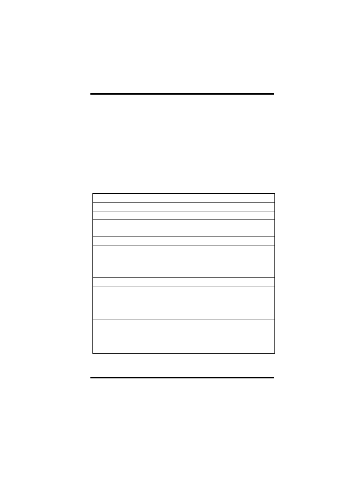
1-3 Motherboard Specification
Form Factor -MICRO-ATX form factor
Board Size -193mm x 244mm
CPU -Supports Socket PGA370-Celeron CPU
System Memory -DIMM 168-pin x 3, SDRAM maximum 768MB
-Support ECC (1-bit error code correct) function
Chipset -Ali Aladdin Pro II Chipset
System Bus/FSB -66/100MHz
-75/83/103/105/110/112/115/120/124/133/140/150MHz
(Available for over-clocking)
Expansion Slots -1 x AGP bus / 3 x PCI bus / 1 x ISA bus
Serial Port -Two serial ports UART 16550 compatible
Parallel Port One parallel port supports:
-SPP-standard parallel port
-EPP-enhanced parallel port
-ECP-extended capabilities port
Floppy Interface Support drivers inches/format with:
-3.5 inches-720KB/1.44MB/2.88MB
-5.25 inches-360KB/1.2MB
IDE Interface -Dual IDE interface support up to four IDE devices
I. PRODUCT INFORMATION
AP0 USER’S MANUAL 1-3
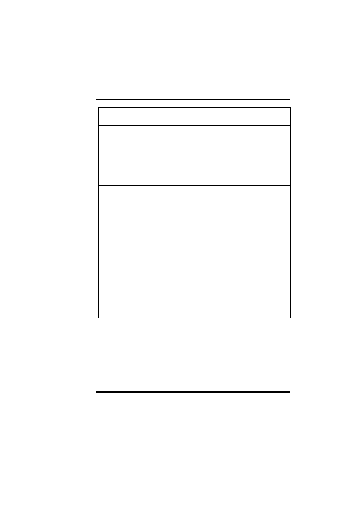
USB Interface -Two USB ports supported
-USB legacy keyboard function supported
PS/2 Mouse -PS/2 mouse supported by connector onboard
PS/2 Keyboard -PS/2 keyboard supported by connector onboard
Sound Integrated C-MEDIA 8338 sound controller compatible
with:
-Sound Blaster Pro
-Adlib
-Microsoft windows system
RTC and Battery -Integrated Ali M5819P RTC chipset
-Lithium (CR-2032) battery
Power On -Panel switch power on
-Keyboard power on
Wake-Up -Modem ring wake up
-LAN wake up
-RTC Alarm Function
Hardware
Monitor -Fan speed monitor-Two fan connectors, warning when
CPU fan, housing fan or system fan is malfunction
-Voltage monitor-Warning when system voltage (5V,
12V, 3.3V, VCORE) are abnormal
-CPU and system thermal monitor-Warning when CPU
and system temperature is higher than a predefined
value
Power
Connector -Supports ATX (20-pin) power connector

I. PRODUCT INFORMATION
1-4AP0 USER’S MANUAL
BIOS -Award BIOS
-Year 2000 Compliance
-PCI 2.1 Compliance
-PnP BIOS v1.0a Compliance
-APM v1.2 Compliance
-DMI 2.0 compliance
-Flash/Upgrade BIOS protection
-Supports ACPI (Advanced Configuration and Power
Interface) and OS Directed Power Management
-Supports SOFT power
-Virus warning supported
-Floppy drive swapping function supported
LED Indicator -System power LED
-HDD activity LED
Other -Support two FAN connectors
Table des matières
Autres manuels EUPA Carte mère


Manuels Carte mère populaires d'autres marques


Telit Wireless Solutions
Telit Wireless Solutions SL869-3DR Manuel utilisateur

Gigabyte
Gigabyte GA-9IVDT Manuel utilisateur

Texas Instruments
Texas Instruments ADS8372EVM Manuel utilisateur

Commell
Commell MS-C73 Manuel utilisateur

IBT Technologies
IBT Technologies MB860 Manuel utilisateur

Nvidia
Nvidia TEGRA DG-04927-001_V01 Manuel utilisateur


