Zikodrive ZDBL30MUL-48 Manuel utilisateur

1
All information contained herein is the exclusive copyright of Round Bank Engineering Ltd and is not to by copied,
duplicated or otherwise distributed without the express permission of Round Bank Engineering Ltd, Unit 7, Victoria
ZDBL30MUL-48 User Manual
Document Number
Revision
Date
Authorised by
1-0116-A
A
03/02/2023
GF

2
All information contained herein is the exclusive copyright of Round Bank Engineering Ltd and is not to by copied,
duplicated or otherwise distributed without the express permission of Round Bank Engineering Ltd, Unit 7, Victoria
Contents
Overview.................................................................................................................................................4
Specifications ..........................................................................................................................................4
Connections ............................................................................................................................................5
Power Supply Connections .................................................................................................................5
Motor Connections.............................................................................................................................5
Analogue Input....................................................................................................................................6
Onboard Pot........................................................................................................................................6
UART Connections ..............................................................................................................................6
Programming Pin Connections............................................................................................................7
UART Control...........................................................................................................................................8
Using the UART ...................................................................................................................................8
Using ZDA010 software to set parameters.............................................................................................9
Getting Started / Setup.......................................................................................................................9
Port Setup .........................................................................................................................................10
Finding the right COM Port...............................................................................................................11
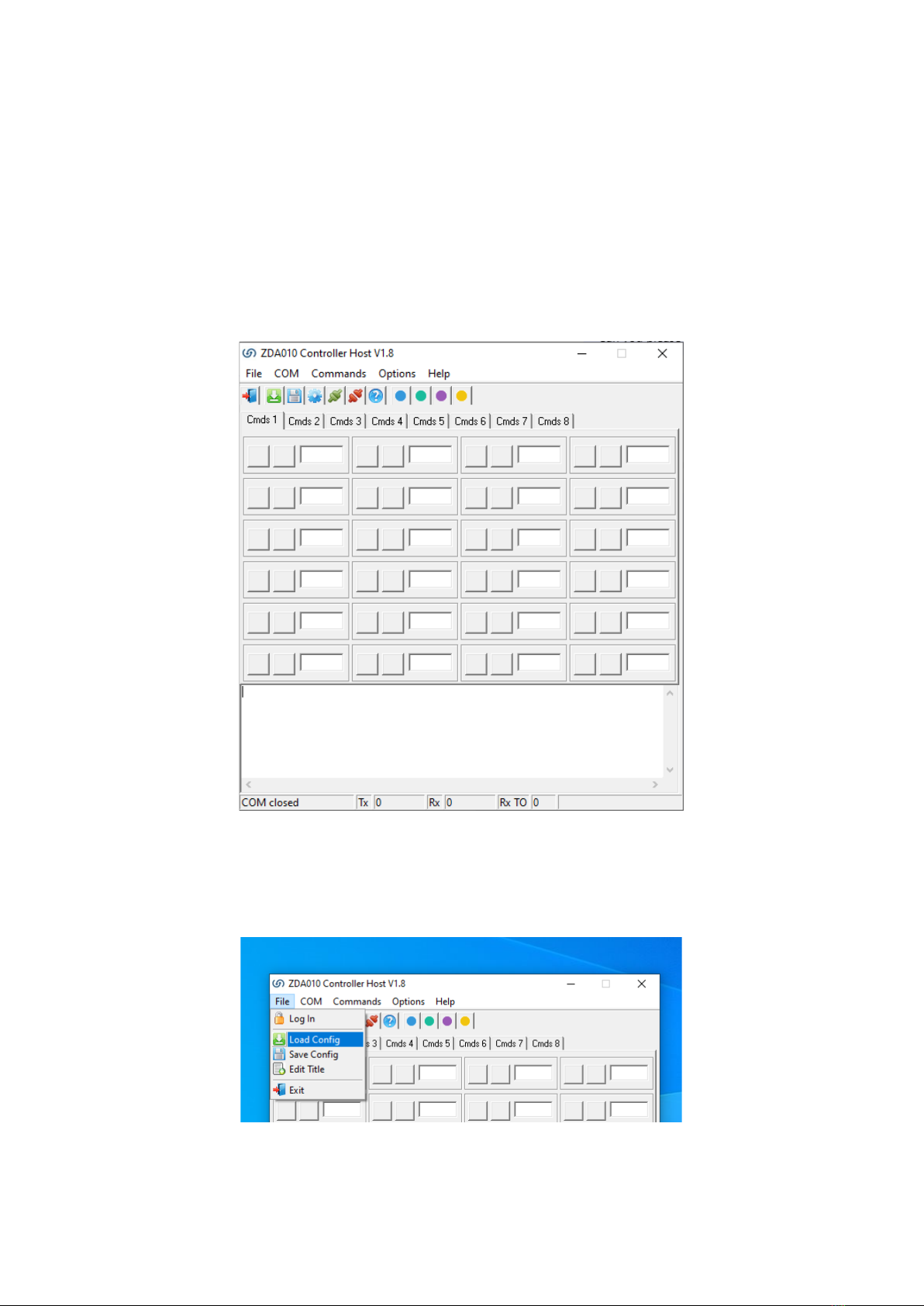
ZDA010 1.8 Overview........................................................................................................................12
Commands and Parameters..............................................................................................................13
General TAB ......................................................................................................................................14
Control Setup TAB.............................................................................................................................15
Drive Setup TAB ................................................................................................................................16
ZDA Commands.....................................................................................................................................17
COM Port Settings.............................................................................................................................17
Sending Commands ..........................................................................................................................17
Writing Commands ...........................................................................................................................17
General Commands ..........................................................................................................................18
Control Setup Commands.................................................................................................................19
Drive Setup Commands.....................................................................................................................20
Command & Parameter Details ............................................................................................................21
Control Setup Data Items..................................................................................................................21
Fault Codes & Fault Data ..................................................................................................................21
Invert Settings...................................................................................................................................21
Start Delay.........................................................................................................................................22
Analogue Scalers (Multiplier and Divider) ........................................................................................22

3
All information contained herein is the exclusive copyright of Round Bank Engineering Ltd and is not to by copied,
duplicated or otherwise distributed without the express permission of Round Bank Engineering Ltd, Unit 7, Victoria
Fixed Speed (%duty)..........................................................................................................................22
Duty Acc/Dec.....................................................................................................................................23
Fixed Speed (PID Hz) .........................................................................................................................23
PID Acc/Dec.......................................................................................................................................23
PID Delay (ms)...................................................................................................................................24
PID Enabled.......................................................................................................................................24
PID Data Items ..................................................................................................................................24
Output Setting...................................................................................................................................25
Bemf Data .........................................................................................................................................25
Data Export Time (ms) ......................................................................................................................25
Drive Data Items ...............................................................................................................................25
PWM Frequency................................................................................................................................26
Min Voltage.......................................................................................................................................26
Max Voltage......................................................................................................................................27
Start PWM.........................................................................................................................................27
Bemf Sum..........................................................................................................................................27
Using the controller ..............................................................................................................................28
Startup...............................................................................................................................................28
Fixed Speed Run................................................................................................................................30
POT Average Run...............................................................................................................................31
Analogue Average Run ......................................................................................................................32

4
All information contained herein is the exclusive copyright of Round Bank Engineering Ltd and is not to by copied,
duplicated or otherwise distributed without the express permission of Round Bank Engineering Ltd, Unit 7, Victoria
Overview
This manual covers the fundamentals of how to setup and use the ZDBL30MUL-48 sensorless
brushless DC motor controller. The manual covers setup and operation of the controller as well as
how to use the ZDA software to set any key parameters.
The controller uses Zikodrive’s ZikoOptimise technology to enable the controller to start motors
quickly and easily and then continuously optimise the drive to handle changes in load, temperature
and other factors.
For more information on this technology, please see our website at www.zikodrive.com
Specifications
Specification
Value
Units
Max Power
1400
W
Rated Power
700
W
Drive Method
High frequency Sensorless Trapezoidal
Min Voltage
8
V
Analogue Input
0-5
V
Operating Temperature Range
-20 to 85
Celsius
Max Voltage
55
V
Running Current
15
A
Max Current
30
A

5
All information contained herein is the exclusive copyright of Round Bank Engineering Ltd and is not to by copied,
duplicated or otherwise distributed without the express permission of Round Bank Engineering Ltd, Unit 7, Victoria
Connections
Power Supply Connections
The power supply connections are the clearly marked on the controller and indicated in the drawing
above. Power supply should be between 8-55VDC and you should set an appropriate current limit (if
using a PSU) to enable adequate power. Setting the current limit too low for your motor will result in
impaired performance and potentially will mean the controller will not start.
NOTE: the controller is protected against reverse polarity, however care should be taken to ensure
the polarity is correct before powering the controller.
DO NOT INCREASE THE VOLTAGE WHILE THE MOTOR IS RUNNING, THE BRAKE WILL BE ENABLED
AND WILL CAUSE THE BRAKE TO BECOME DAMAGED.
Motor Connections
Motor connections are on the opposite side of the controller to the power supply inputs. They are
clearly marked on the controller. Take care to match the motor phases with their appropriate
connection. Wiring the motor incorrectly may result in the motor not functioning or the motor
running in the opposite direction to that intended. The motor manufacturer should supply the wire
colour / motor phase information on the motor datasheet.

6
All information contained herein is the exclusive copyright of Round Bank Engineering Ltd and is not to by copied,
duplicated or otherwise distributed without the express permission of Round Bank Engineering Ltd, Unit 7, Victoria
Analogue Input
The analogue input is marked on the drawing above and is found on the pin header.
Connect the external analogue input between the “GND” and the “0-5V” connections
The analogue input runs through an RC low pass filter. This provided discrete filtering of the
analogue signal to ensure the signal is not affected by noise, as well as introducing a hardware slew
rate of the input signal.
NOTE: applying voltages over 5V to this input can permanently damage the controller. Take care
to ensure you have this correctly.
Onboard Pot
The onboard pot is marked on the drawing above and can be used to adjust speed if required.
NOTE: the onboard pot is a small trimmer pot and is not designed for constant adjustment. Care
must be taken when adjusting this that you do not over turn the pot as this can break the end
stops and lead to permanent damage.
UART Connections
The UART connections are highlighted on the wiring diagram above. These accept a max voltage of
3.3V on the RX or TX pins.
NOTE: applying voltages in excess of this will lead to permanent damage.
3V3 max voltage on either the RX or TX pins. The UART connections can be connected directly to
another microcontroller, or connected to a PC Serial Port using an FTDI cable “TTL-232R-3V3”. This
can be purchased on line at www.zikodrive.com.
NOTE: Ensure the RX and TX lines are crossed over to enable correct communication. Ie, TX from
PC goes to RX of the controller, and RX from PC goes to TX of the controller. Also, ensure a
common GND between the devices.
If another Microcontroller is used for communication, ensure the distance between the devices is
kept as short as possible and twisted pairs of the RX and TX lines are used. Contact us @
www.zikodrive.com for any additional information with regards to the UART ZDA protocol for the
ZDBL30MUL-48.

7
All information contained herein is the exclusive copyright of Round Bank Engineering Ltd and is not to by copied,
duplicated or otherwise distributed without the express permission of Round Bank Engineering Ltd, Unit 7, Victoria
Programming Pin Connections
These should not be needed in general use but if you have requested a custom program for a
specific application then these pins will need to be used. If this is the case we will supply separate
information on how to do this.

8
All information contained herein is the exclusive copyright of Round Bank Engineering Ltd and is not to by copied,
duplicated or otherwise distributed without the express permission of Round Bank Engineering Ltd, Unit 7, Victoria
UART Control
The UART connections are used to set up all the required user-settable parameters.
Please note that all parameters will be stored in EEPROM, this means that they are non-volatile and
the controller will remember these settings when the power is disconnected.
Zikodrive will provide an “ini” (Config) file that can be uploaded into ZDA software that can be used
to modify settings and parameters to suit the required application. These “ini” (Config) files can be
modified and saved for each of the application requirements using ZDA. The standard version of this
file is available for download from www.zikodrive.com.
Using the UART
The UART communication can be operated from any serial terminal program or microcontroller. If
you have a specific requirement for this or require any assistance please contact us directly and we
can advise on how best to achieve your requirements.
UART COM Port settings for the ZDBL30MUL-48:
Baud Rate: 115200, Data bits = 8, Parity = None, Stop bits = 0.

9
All information contained herein is the exclusive copyright of Round Bank Engineering Ltd and is not to by copied,
duplicated or otherwise distributed without the express permission of Round Bank Engineering Ltd, Unit 7, Victoria
Using ZDA010 software to set parameters
Getting Started / Setup
Open the .exe file from Zikodrive. Depending on your security settings you may be asked to verify
that the “.exe” file has come from a verified source. You will need to approve this with your security
system. Once open you should see a screen as below.
When first opened, the ZDA will be blank. You will need to open the initial “.ini” (Config) with the
settings of the required motor/pump/application created by Zikodrive. To do this, Click File > Load
Config and then locate the file location where the .ini file was saved (see below).

10
All information contained herein is the exclusive copyright of Round Bank Engineering Ltd and is not to by copied,
duplicated or otherwise distributed without the express permission of Round Bank Engineering Ltd, Unit 7, Victoria
Port Setup
On the main menu at the top of the page, select “COM” and then “Settings”.
You should then get the screen below. Ensure the settings are as below (with the exception of the
COM port which will vary depending on which port you have used on your device).
The first time the .ini (Config) file is loaded, it will attempt to open the COM Port number that was
previously saved in the .ini file. Please note that this may be incorrect when first using the software.
It is nonetheless a simple change to make. Simply close the COM port by selecting “COM” and
“Close”. Then open the “Settings” option, change the COM port to the correct one and then select
“COM” and “Open”.
NOTE: every time you wish to change COM port, you must ensure you close the COM port, change
it, then Open the correct one.
Table des matières
Autres manuels Zikodrive Matériel informatique
Manuels Matériel informatique populaires d'autres marques

EMC2
EMC2 VNX Series Manuel du propriétaire

Panasonic
Panasonic DV0PM20105 Manuel utilisateur

Mitsubishi Electric
Mitsubishi Electric Q81BD-J61BT11 Manuel utilisateur

Gigabyte
Gigabyte B660M DS3H AX DDR4 Manuel utilisateur

Raidon
Raidon iT2300 Manuel utilisateur

National Instruments
National Instruments PXI-8186 Manuel utilisateur


