Workhorse Mach Series Manuel utilisateur
Owner’s Manual
Mach Series
3730 E. Southern Avenue, Phoenix, AZ 85040 USA
800-778-8779 Workhorseproducts.com 1

Table of Contents
3730 E. Southern Avenue, Phoenix, AZ 85040 USA
800-778-8779 Workhorseproducts.com 2
I. Introducon …………..…………………………...………………….……….…….……….. 3
II. Specicaons …..……………..………………………...………….………..………….…. 4
III. Parts for Assembly …..……………..……………………….….………….…….………. 5
IV. Assembly
Step 1: Inserng Levelers and Casters ……..……………………….…….……… 6
Step 2: Installing the Print Head …………………………………….….…….……. 7
Step 3: Installing the Print Arms ……….………………..………………...….……. 8
Step 4: Aaching the Platens …………………….…………..…………….…..……. 9
V. Print Head and Micro Adjustments ……………………..………………...…...…. 10
VI. Maintenance and Troubleshoong …………………………….………….…...… 12
VII. Parts List …………………………………………………………………………..……....… 13
VIII. Limited Warranty ………………………………………………………….………….… 14

Introducon
3730 E. Southern Avenue, Phoenix, AZ 85040 USA
800-778-8779 Workhorseproducts.com 3
Congratulaons on your purchase of the Mach Series.
Check the crate for damages. DO NOT accept the crate if there are any damages caused by improper han-
dling during shipping. Immediately report any damages to the carrier and contact Workhorse Products at,
800-778-8779.
Be sure to inspect the crate contents IMMEDIATELTY, while the carrier is sll present. Even though our pack-
aging has been designed to handle normal shipping condions, we cannot foresee damages done by the car-
rier. We will not be responsible for damages that occur during transportaon.
If there are damages immediately nofy the driver, le a claim with the carrier and call Workhorse Products.
The Importance of the Owner’s Manual:
The purpose of the Owner’s Manual is to familiarize you with the parts and operaons of the Mach Series.
There are step-by-step instrucons to assemble the press, accompanied with links to videos for further assis-
tance. Also included are explanaons of the product’s key features, and addional informaon that will help
with the maintenance of your press.

Specicaons
3730 E. Southern Avenue, Phoenix, AZ 85040 USA
800-778-8779 Workhorseproducts.com 4
4 Color, 4 Staon
Max Screen: 32" (81CM)
Dimensions: 103” x 34-36”
M-44-M
8 Color, 6 Staon
Max Screen: 21" (53CM)
Dimensions: 111” x 34-36”
M-86-O
6 Color, 4 Staon
Max Screen: 23" (58CM)
Dimensions: 103” x 34-36”
M-64-O
6 Color, 6 Staon
Max Screen: 26" (66CM)
Dimensions: 111” x 34-36”
M-66-M
8 Color, 8 Staon
Max Screen: 26" (66CM)
Dimensions: 130” x 34-36”
M-88-O
10 Color, 8 Staon
Max Screen: 23" (58CM)
Dimensions: 130” x 34-36”
M-108-O

Parts for Assembly
3730 E. Southern Avenue, Phoenix, AZ 85040 USA
800-778-8779 Workhorseproducts.com 5
Descripon Part Number
Print Arm Pre-Assembled
Platen (15” x 18”) 12015
Print Head Spring 71010
Nylon Neng 10-8000
Hog Ring 71007
Hex Bolt (1.25” x
40mm)
41-HTB-M8-20
Descripon Part Number
1/2” Flat Washer 43-FLT-M12-10
Roll Pin 45-1260
Base Pre-Assembled
Hex Bolt (1.5”x 25mm) 41-HB-M10-20
Leg Levelers (1.75”x
60mm)
41-HTB-M12-30
The quanty of parts diers depending on the specic model being assembled. In this manual a 6 Color/ 4
Staon Mach Series Manual Press is being assembled. The quanty of parts will not match if assembling
another model of the product.
Assembly
3730 E. Southern Avenue, Phoenix, AZ 85040 USA
800-778-8779 Workhorseproducts.com 6
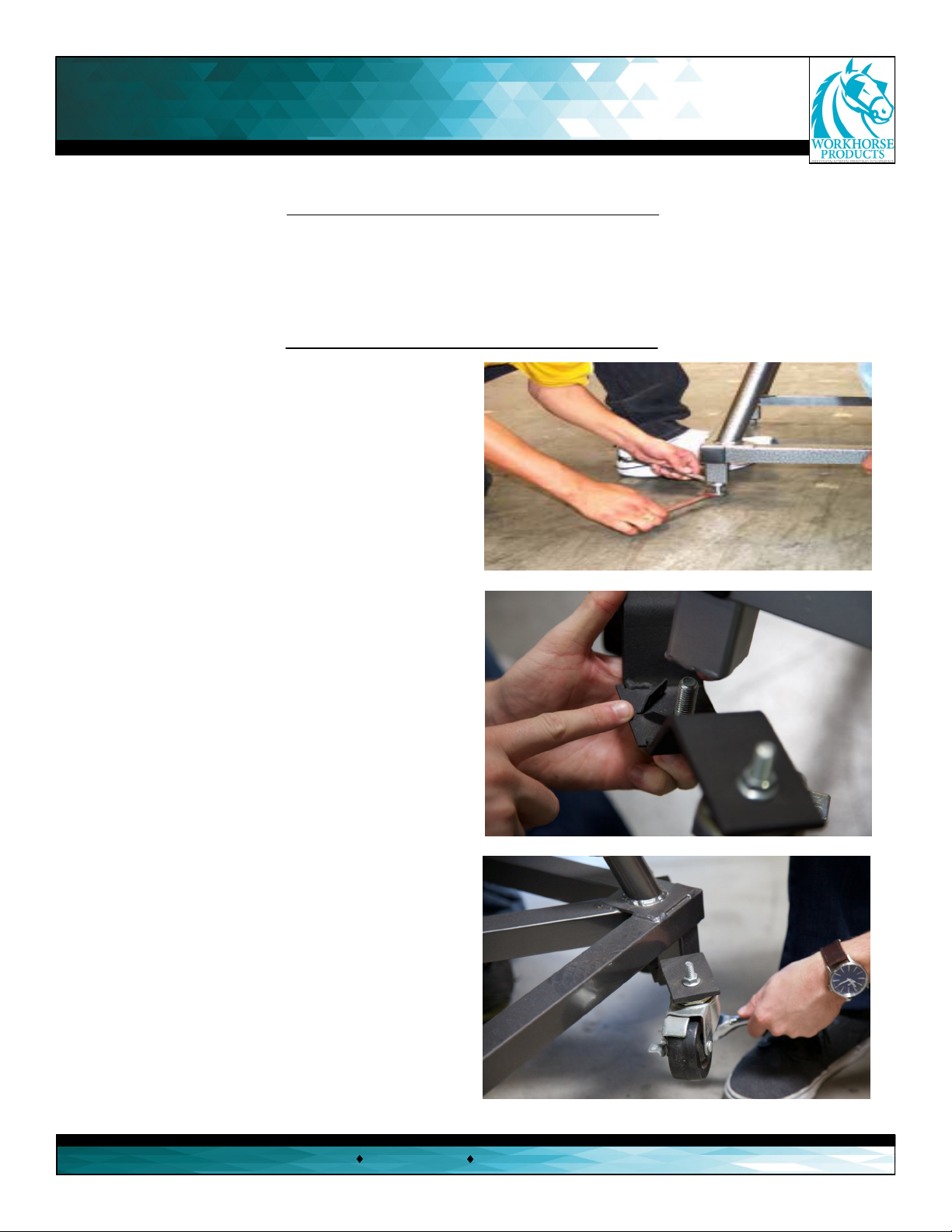
Step 1: Inserng levelers/casters.
Tools needed:
3/4” Wrench and
Socket
3/4” Wrench and
Socket
Parts needed:
4 x Levelers/Casters
Base
1. Install the leveling nut onto the leveling bolt unl
it’s 1” from the bolt head. When installing the levelers
ensure that they are all the same height. Use a 3/4”
wrench on the head of the bolt and a 3/4” wrench on
the nut to ghten. Repeat this process for each leg on
the press
2. To install the caster system thread the top of the
bolt into the boom of the press, where the levelers
would be installed. Thread unl the very boom.
3. Aer the casters are threaded by hand, use a 3/4”
deep socket wrench to ghten.

Assembly
3730 E. Southern Avenue, Phoenix, AZ 85040 USA
800-778-8779 Workhorseproducts.com 7
Step 2: Installing the print head.
5. Aer both springs and hog rings
are aached, push down the print
head to insert a stop bolt with a 1/2”
washer into the upper hole of the
print head.
6. Screw on a 1/2” washer and a lock
nut onto the other side of the bolt.
Tighten the stop bolt by hand as much
as possible. Repeat steps 1-6 for every
print head on the press.
Parts needed:
6 x Stop Bolts
12 x Hog Rings
12 x Nylon Nengs
12 x 1/2” Flat Washers
12 x Lock Nuts
1. Raise the print head and insert
a spring into the boom-le hole
of the aachment arm bracket.
2. Cover the spring with nylon
neng and leave the top of the
spring exposed.
3. Connect the hog ring to the
spring and then hook the hog ring
onto the print head. Use the hole
closest to the print head.
4. Pull the nylon neng over
the hog ring to cover the enre
assembly. Repeat steps 1-3 for
the other side of the print
head.

Assembly
3730 E. Southern Avenue, Phoenix, AZ 85040 USA
800-778-8779 Workhorseproducts.com 8
Step 3: Installing the print arms.
Tools needed:
Hammer
3/4” Socket
Wrench
Parts needed:
16 x Hex Bolts (1.5” x 25mm)
16 x Flat Washers (1/2”)
8 x Roll Pins
1. It’s very important to match the
numbers on the print arm with the
numbers on the base. These are factory
set for proper leveling and alignment.
Align the holes on the print arm with
the holes on the base.
2. Insert a bolt (1.5”x 25mm)
and 1/2” at washer into the
top-right corner rst and the
boom-le corner second.
Only ghten by hand for now.
3. Insert a roll pin into the middle-right
hole rst, followed by the middle-le hole
second. Aer both pins are inserted by
hand, lightly hammer them so it inserts
into the hole of the press base. Leave 1/4
of the pin exposed.
4. Aer both spring pins are installed, insert the other
two hex bolts and at washer so that every corner hole
is lled.
5.Aer installing the two bolts with the washers, ghten
them with a 3/4” socket wrench. Do not overghten to avoid
compressing the print arm. Repeat steps 1-5 for every print
head. Don’t adjust the bolts on the support arm, which are
located under the print arm.

Assembly
3730 E. Southern Avenue, Phoenix, AZ 85040 USA
800-778-8779 Workhorseproducts.com 9
Step 4: Aaching the platens.
Parts needed:
Platens
1. Lower one of the print heads and slide
the platen onto the print arm unl it’s 1/2”
from the end of the screen clamp. Securely
ghten the boom knob. Repeat for every
print head.
Congratulaons! The Mach Series is now
fully assembled.
Remember, don’t adjust the bolts and nuts located on the support arms. They are factory set for proper
leveling and alignment. One of the many advantages of the Mach Series is that when it’s manufactured it’s
also fully assembled, making it leveled and inspected at the factory. This quality control process is to ensure
success when assembling the press on locaon.

Print Head and Micro Adjustments
3730 E. Southern Avenue, Phoenix, AZ 85040 USA
800-778-8779 Workhorseproducts.com 10
(A) O Contact Adjustment Knob
(B) X and Y Micro Adjustments
(C) Micro Lockdown Knobs
(D) Side-to-Side Adjustment
(E) O Contact Jam Knob
(F) Screen Lockdown Knobs
(G) O Contact Clamp & Screen Holder
(H) Screen Tilt Adjustment
(H1) Screen Tilt Jam Nut
(H2) Screen Tilt Ring
(I) O Contact Foot Pad
Adjusng the O Contact: (A, E & I)
Even though the Mach is automacally set at a
standard o contact, there will be instances that
require adjusng it. To adjust, loosen the o contact
adjustment knob (A) and unscrew/screw down the
o contact adjustment knob to adjust the foot pad
(I) to the desired o contact. Tighten the jam knob
(E) to prevent the o contact knob (A) from moving,
avoid over ghtening.
(A)
(C) (B)
(B)
(C)
(D)
(D)
(E)
(F)
(F)
(G)
(H)
(H1)
(H2)
(I)
(B) (B)
Adjusng the Screen Tilt: (H, H1, & H2)
First, loosen the screen lt jam knob (H1) to create
room to adjust the screen lt and loosen the screen
lt knob (H). Hold the screen and lt it so that the
screen is parallel with the pallet. Then ghten the
screen lt jam knob (H1) unl it’s against the
screen lt ring (H2). While holding the screen lt
jam knob, ghten the screen lt knob unl it ght-
ens the screen lt jam knob against the screen lt
ring.
Tip: To set the o contact consistently, use two 16x1”
10mm strips of plasc for each distance. Place one strip
on the platen and one at the front and back of the
screen ,adjust the screen lt (H) unl it makes contact
with both strips. This will ensure that the front of the
screen is parallel with the back of the screen.
Ce manuel convient aux modèles suivants
6
Table des matières
Autres manuels Workhorse Outils électriques


