Well Tempered Lab Amadeus MK II Manuel utilisateur

1
INSTRUCTION MANUAL
Amadeus MK II
Rev. August 2013

2
Preliminary
Before embarking on the relatively simple process of assembling the Amadeus MK II, please
take the time to fully read these instructions and follow the steps within. The old adage of "if
all else fails read the instruction manual" needs to be applied from the onset. The Well
Tempered Lab cannot be held responsible for consequences resulting from the failure to
comprehend these instructions. If in doubt always consult with your dealer.
The Well Tempered Lab’s policy is the continuous improvements of its products. We
therefore reserve the right of departure from illustration or specification that this might
Unpacking the Amadeus MK II
Contents
Assembly
Installing the Platter
Pg 3
Installing the Belt
Speed adjustments
Pg 8
Fitting the Cartridge and Tonearm adjustments
Pg 8
Rear Panel
Troubleshooting
Pg 10
Tonearm Alignment Guide for Well Tempered Lab Turntables
Pg 11
Warranty and Service
Pg 12
European Waste and Electrical and Electronic Directive
Pg 13 - Pg 14
Pg 3 - Pg 4
Suspending the Symmetrex Tonearm
Pg 9 - Pg 10
Making a Belt
Pg 15
Pg 18
Pg 4 - Pg 6
Pg 7 - Pg 8
Registration
Pg 18
Stylus Pressure Gauge
Pg 18
3
Unpacking the Amadeus MK II
We recommend the use of the white gloves provided when handling the plinth and platter
assemblies.
Take care that none of the fluids contaminate the finished surfaces of your Amadeus MK II.
The Amadeus MK II packaging has been designed to protect it from the hazards of shipping. It is
advisable to save it for further use.
Important: Never place a Well Tempered Lab turntable in direct sunlight. Not only will it have
detrimental effects on your valuable recordings, it will impair the mechanical integrity and
performance of your turntable.
Assembly
For ease of assembly we recommend a flat work surface, such as a table or bench. All necessary
tools have been provided.
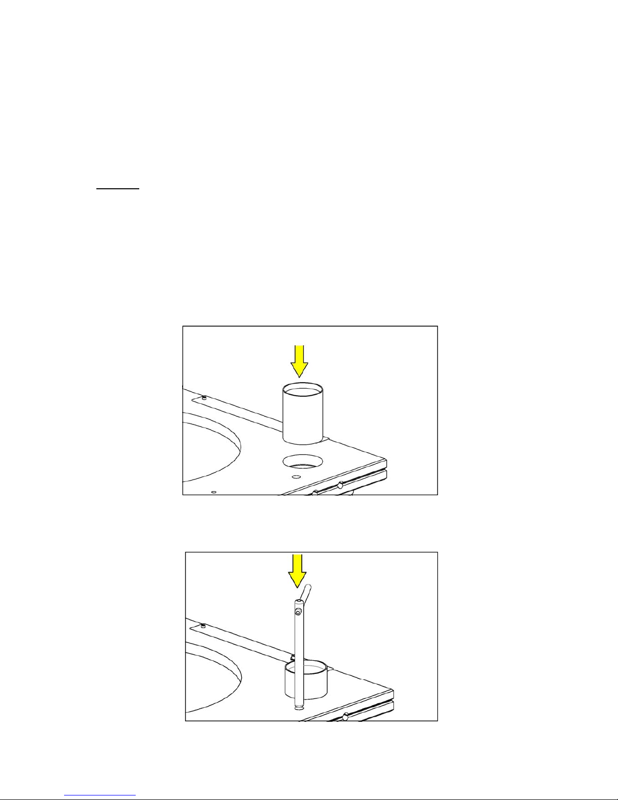
1. Install bearing cup in plinth adjust to approx 40mm (1.6in) above plinth and tighten set screw. See
Fig (1).
2. Install tonearm suspension pillar to approx 95mm (3.8in) above plinth and tighten set screw.
Complete with tonearm suspension rod. See Fig (2).
Fig (1)
Fig (2)

4
3. Install tonearm rest / lock in plinth approx 50mm (2in). See Fig (3)
Fig (3)
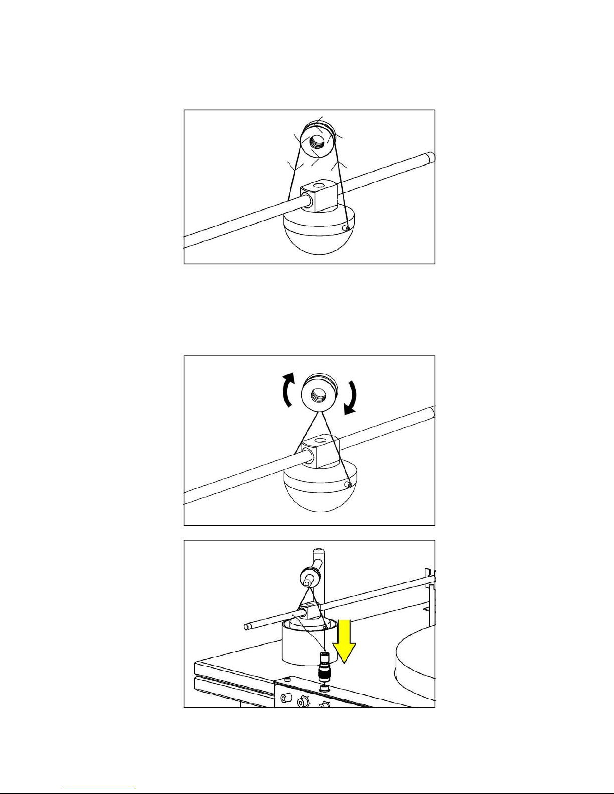
Suspending the Symmetrex Tonearm
Before embarking on this procedure, we suggest a review of the manual from Fig (4) - (9) is
mandatory.
1. Coarse azimuth adjustment if necessary can be achieved by rotating the tonearm within the golf
ball. The Headshell should be parallel to the small nylon filament points. See Fig (4).
Fig (4)
*Front-on view of Symmetrex tonearm
Parallel
Headshell
Note: There is no requirement to apply excessive force to the above set screws. A gentle tighten is
sufficient to secure the components. Over tightening can lead to damaging the plinth.
5
3. Correct bridle length when tonearm is suspended is approximately 25mm from top of tonearm to
bottom of suspension rod. See Fig (6). Apply a clockwise half twist to the azimuth adjustment collar
and install on the suspension rod. The half twist on the nylon suspension effectively applies the
correct “anti-skate”. See Fig (6) - (8). Correct azimuth adjustment is achieved by rotating the azimuth
collar in the directions of the arrows.
Fig (6)
2. With a small amount of care take tonearm and apply one and a half turns of the nylon suspension
from the golf ball around the azimuth adjustment collar. See Fig (5).
Fig (5)
Fig (7)
6
5. Adjust pillar, rod and azimuth collar to allow golf ball to float central of bearing cup.
Note: All the above adjustments can be fine tuned when cartridge is installed.
6. Fit tonearm connector to socket making sure that the connector "locks" in place, failure to ensure
this connector is firmly locked may result in a loss of signal on either channel. See Fig (9)
Fig (9)
Fig (7)
Fig (8)
7
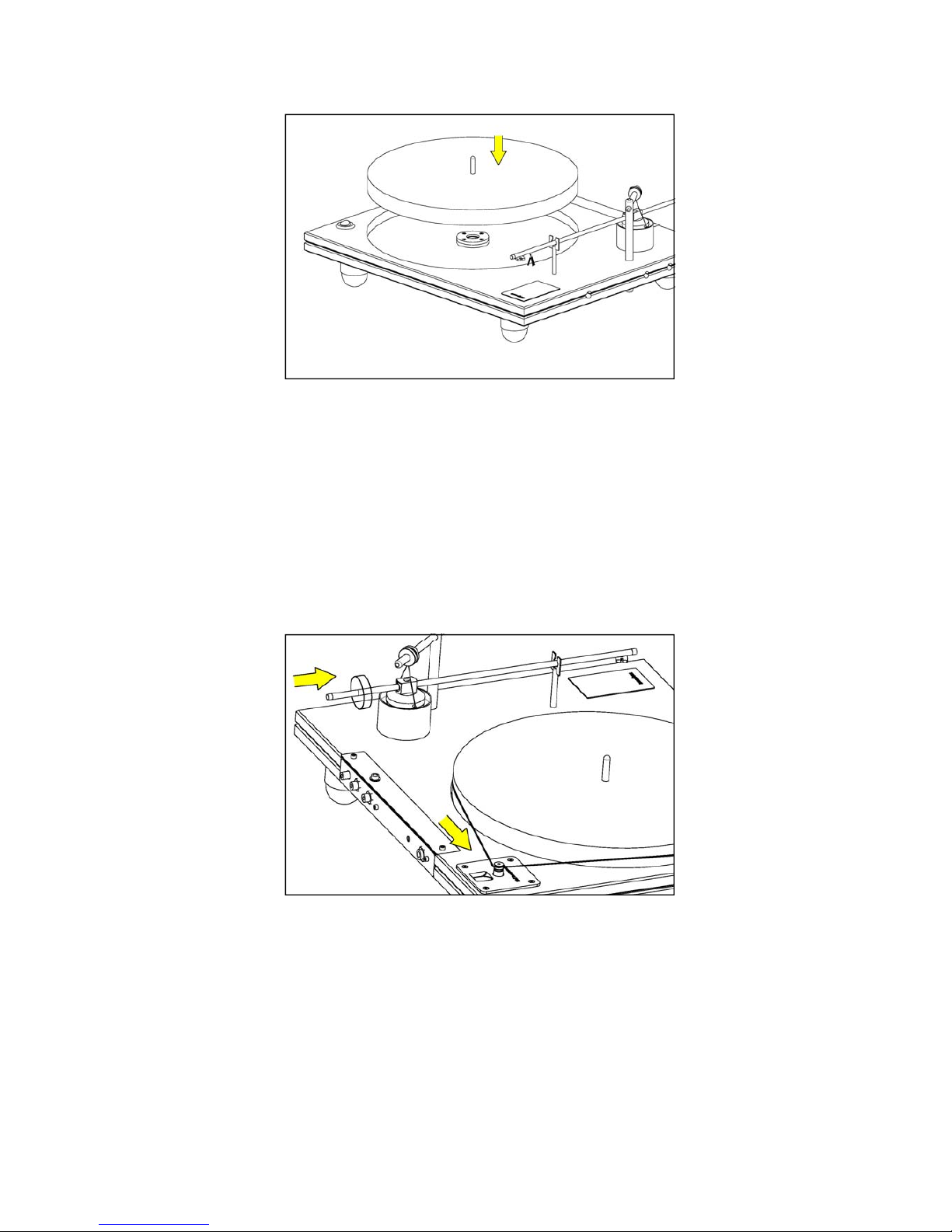
Installing the Platter
Please ensure that the point of the triangle hold in the upper teflon bearing is correctly orientated to
the motor pulley. See Fig (10). If necessary consult your dealer.
Fill the bearing with synthetic oil supplied to a level of approx 5mm (1/4”) above the bottom Teflon
bearing, this is not critical. Do not overfill. Over-filling the bearing will cause the oil to overflow the
bearing housing when the platter spindle is lowered into the bearing housing. Gently lower platter into
bearing. See Fig (11) - (12). It is most important that spindle is located correctly in the centre of the
lower thrust bearing. Failure to locate the pivot point of the spindle correctly will cause the platter to
rotate abnormally. The spindle has been designed to protrude through the platter to provide a central
lifting point that enables the user to easily achieve this.
Important: The unique design of the zero clearance Well Tempered Lab top bearing allows the
spindle to be virtually “free standing”. It is perfectly normal for the platter to tilt away from the motor
when the belt has not been installed.
Should there be any necessity to replace the bearing oil, any synthetic motor oil of any brand within a
viscosity range of 5W-50 is acceptable.
Note: The zero clearance Well Tempered bearing can rotate for hours without oil. If you wish, you
can complete other adjustments before applying the bearing oil. See Fig (10).
Fig (11)
Fig (10)
8
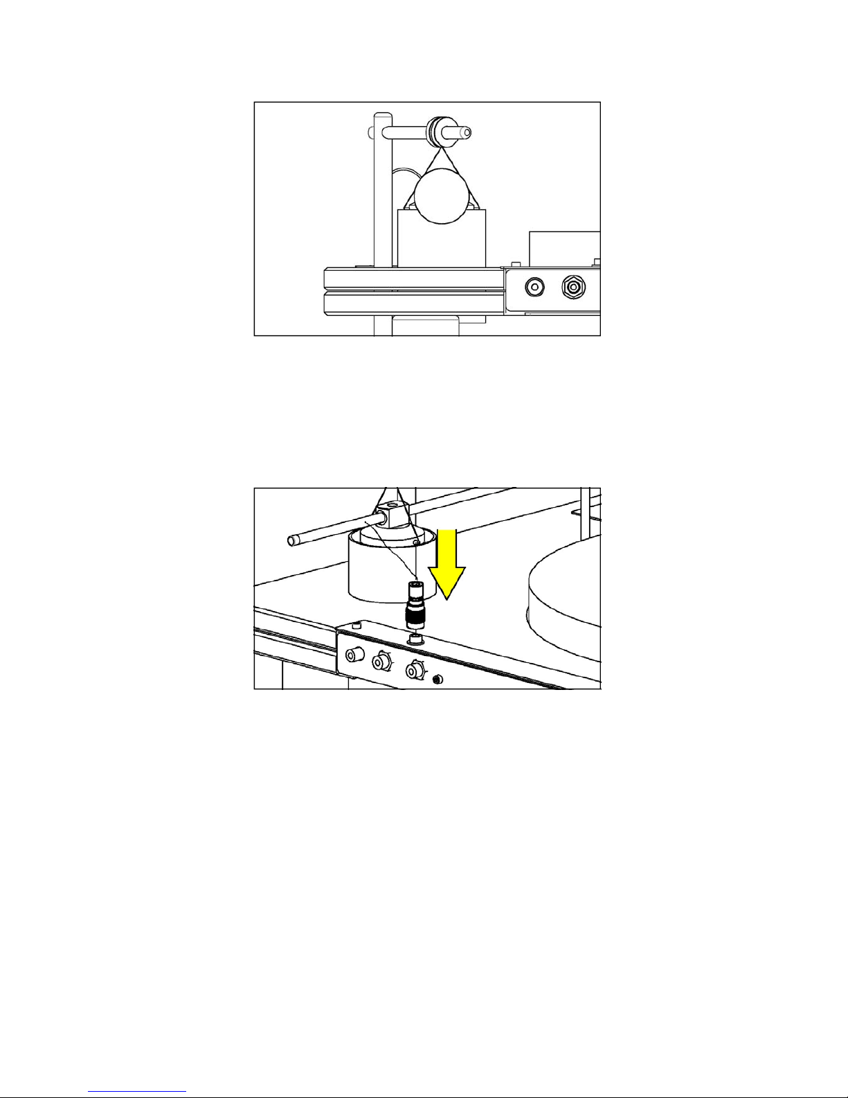
Speed Control
Speed change is effected by manual movement of the belt on the pulley. 33.5 RPM on the small
diameter step on the pulley, 45 RPM on the larger diameter step on the pulley.
Installing the Belt
Start with the belt around the motor pulley, take care the other end clears the centre spindle and
rotate the platter, the belt will track around the platter. See Fig (13). Well Tempered Lab belts if
dropped are easily misplaced, we give you two but suggest you place the belt on something dark to
make it easily seen.
Fig (13)
Speed Adjustment
This is factory set, but if required, this can be achieved by carefully adjusting the small screw
adjacent to the DC socket.
Fig (12)
9
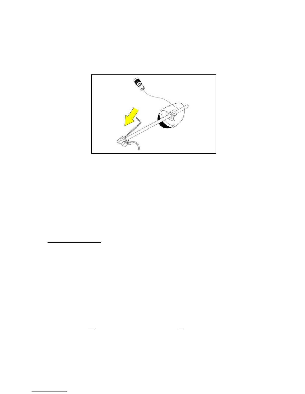
Fitting the Cartridge and Symmetrex Tonearm adjustments
1. We recommend fitting the cartridge with the tone arm in position. However it is possible to fit the
cartridge before suspending the tone arm (see Fig 14). Great care needs to be taken when installing
the cartridge as the Well Tempered Lab bears no responsibility for cartridge damage.
Fig (14)
2. Install the cartridge to the manufacturer’s specifications. The Amadeus MK II features a head shell
that requires no tracking alignment adjustment. We strongly recommend it remains firmly fixed in the
correct position as supplied.
3. The Amadeus MK II Symmetrex tonearm has an effective length of 10.5” (267 mm). The headshell
is fixed ex-factory in the optimum position. There is no provision for over-hang adjustment. Some
alignment protractors may well disagree. However, The Well Tempered Lab stands by their
convictions.
Important: There is absolutely no reason to torque headshell/cartridge mounting hardware to
excess. Cartridge mounting hardware only requires firm but gentle tightening. Heavy handed
torquing of mounting hardware can result in movement of the Amadeus headshell (refer to
www.welltemperedlab.net on tracking geometry).
4. There is an optional finger lift provided which can be attached to the cartridge fixing screw,
adjacent to the right hand side of the plinth.
5. Apply enough damping fluid so as that no more than one third of the golf ball is submerged in fluid.
See Fig (15).
Note: Damping can be altered by simply raising or lowering the damping cup, it is not critical and
maybe adjusted to suit the listener’s own preference.
6. Set tracking force with stylus gauge, supplied to cartridge manufacturer’s specification.
7. To set tracking force, two counterweights are supplied to enable correct tracking force to be
applied to cartridges of various weights. We recommend choice of counterweight (s) that allow
correct tracking force to be obtained with weight (s) as close to the tonearm lead out cable as
practicable. This is not critical but care needs to be taken as to not damage tone-arm lead out cable
when attaching counterweights to tone-arm.
8. Adjust tonearm for correct VTA by set screw on suspension pillar.
10
9. Correct Azimuth can be obtained by gently rotating the azimuth adjustment collar to allow the
cartridge to track parallel to the record surface. This can be achieved whilst the record is rotating and
requires only minor correction in both directions to achieve the correct result.
10. Due to the viscosity of the damping fluid adjustments in both tracking force and azimuth require
the tonearm to momentarily “settle” to effect the correct results.
Fig (15)
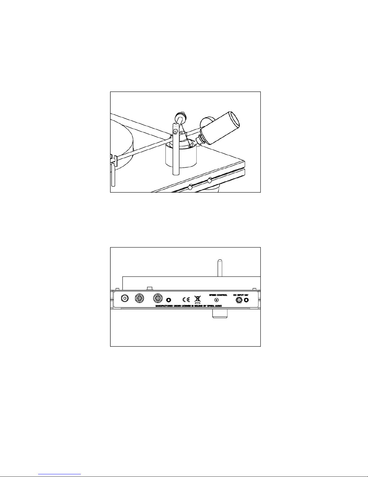
Rear Panel
Earth screw and phono sockets colour coded and clearly marked are on the rear panel. See Fig (16).
Speed adjustment is also available on this panel. Connection for the AC adaptor is on this panel and
clearly marked. Plug it in, you are ready to go. Enjoy!
Fig (16)
Table des matières
Autres manuels Well Tempered Lab Platine

Well Tempered Lab
Well Tempered Lab Amadeus 254 Manuel utilisateur

Well Tempered Lab
Well Tempered Lab Royale 400 Manuel utilisateur

Well Tempered Lab
Well Tempered Lab Simplex MK II Manuel utilisateur

Well Tempered Lab
Well Tempered Lab Amadeus Manuel utilisateur

Well Tempered Lab
Well Tempered Lab Amadeus GTA MK II Manuel utilisateur

Well Tempered Lab
Well Tempered Lab LTD Manuel utilisateur


