Watlow F4T Manuel utilisateur

0600-0092-0000 Rev. B Made in the U.S.A.
March 2015
User’s Guide
Registered Company
Winona, Minnesota USA
ISO 9001
TOTAL
3 Year Warranty
CUSTOMER
SATISFACTION
F4T Controller
Installation and Troubleshooting
1241 Bundy Boulevard., Winona, Minnesota USA 55987
Phone: +1 (507) 454-5300, Fax: +1 (507) 452-4507
http://www.watlow.com/F4T.cfm

Safety Information
We use note, caution and warning symbols throughout this document to draw your attention to
important operational and safety information.
A “NOTE” marks a short message to alert you to an important detail.
A “CAUTION” safety alert appears with information that is important for protecting your
equipment and performance. Be especially careful to read and follow all cautions that
apply to your application.
A “WARNING” safety alert appears with information that is important for protecting you,
others and equipment from damage. Pay very close attention to all warnings that apply to
your application.
The safety alert symbol, (an exclamation point in a triangle ç) precedes a general
CAUTION or WARNING statement.
The electrical hazard symbol, (a lightning bolt in a triangle
Ó
) precedes an electric shock
hazard CAUTION or WARNING safety statement. Further explanations follow:
Symbol Explanation
ç
Ó
CAUTION: Warning or Electrical Hazard that needs further explana-
tion than label on unit can provide. Consult QSG for further infor-
mation.
AVERTISSEMENT: mise en garde ou danger qui demande plus de
précisions que l’information sur l’étiquette de l’unité. Consultez le
manuel de l’utilisateur pour plus d’informations.
Unit can be powered with either alternating current (ac) voltage or
direct current (dc) voltage.
ESD Sensitive product, use proper grounding and handling tech-
niques when installing or servicing product.
Do not throw in trash, use proper recycling techniques or consult
manufacturer for proper disposal.
Enclosure made of Polycarbonate material. Use proper recycling
techniques or consult manufacturer for proper disposal.
Unit is a Listed device per Underwriters Laboratories®. It has been
evaluated to United States and Canadian requirements for Process
Control Equipment. UL 61010 and CSA C22.2 No. 61010. File
E185611 QUYX, QUYX7. See: www.ul.com
Unit is compliant with European Union directives. See Declaration
of Conformity for further details on Directives and Standards used
for Compliance.
Unit has been reviewed and approved by Factory Mutual as a
Temperature Limit Device per FM Class 3545 standard. See: www.
fmglobal.com
CAUTION
WARNING
Electrical
Shock Hazard
or

Symbol Explanation
Unit has been reviewed and approved by CSA International for use
as Temperature Indicating-Regulating Equipment per CSA C22.2 No.
24. See: www.csa-international.org
This F4T User’s Guide is copyrighted by Watlow Electric Manufacturing Company, © March 2015
with all rights reserved.
• © 2010-2012, QNX Software Systems Limited. All rights reserved.
• © 2008 -2014, Crank Software Inc. All rights reserved.
• Watlow®and TRU-TUNE®are registered trademarks of Watlow Electric Manufacturing
Company.
• UL®is a registered trademark of Underwriter's Laboratories Incorporated.
• Modbus®is a registered trademark of Schneider Automation Incorporated.
• Vaisala®is a registered trademark of Vaisala OY Corporation.
• Microsoft®and Windows®are registered trademarks of the Microsoft Corporation.
Quencharc®is a registered trademark of ITW Paktron.

Watlow F4T Install & Troubleshooting •1 • Table of Contents
TC Table of Contents
Chapter 1: Overview .....................................2
Available F4T Literature and Resources .........................2
Chapter 2: Install and Wire.................................5
Getting Started Quickly...The Logical Approach ...................5
Dimensions...............................................5
Installing the F4T ..........................................6
Panel Mounting the Base.................................6
Flush Mounting the Base.................................7
Electrical Isolation .........................................9
Wiring the F4T Base ........................................9
Power Requirements ......................................10
Flex Module (FM) Characteristics .........................10
Flex Module Installation ....................................10
Wiring the Modules .......................................11
Communications Connections............................25
Chapter 3: Connecting a PC ...............................26
Using the User Interface (UI) to Change or View Ethernet Settings ... 26
Understanding the Front Panel Navigational Buttons ..........26
DHCP Connection .....................................28
Fixed IP Connection....................................28
Starting Composer Software .............................29
Verifying Pluggable Flex Module Installation Using Composer ...29
Chapter 4: Calibration ...................................31
Calibrating the F4T ........................................31
Required Equipment When Performing Calibration ...............31
Calibration of Analog Inputs .................................32
Using Composer Software to Calibrate Analog Inputs .............33
Using the User Interface to Calibrate Analog Inputs...............33
Chapter 5: Troubleshooting................................34
Replacing the Battery ......................................40
Chapter 6: Appendix ....................................42
F4T Base Specications ..............................42
F4T Base Ordering Information .....................45
Flex Modules and Limit I/O Specications ................46
Flex Module - Mixed I/O Ordering Information ..........49
Flex Module - Limit Ordering Information..............50
Flex Modules - High Density I/O Specications ............50
Flex Module - High Density Ordering Information .......54
Flex Module - Communications Ordering Information ....54
How to Reach Us .........................................57

Watlow F4T Install & Troubleshooting •2 •Chapter 1 Overview
Chapter 1: Overview
1
Available F4T Literature and Resources
Document Title and Part Number Description
F4T Setup and Operation User Guide,
part number: 0600-0093-0000
This document looks deeper at the system con-
figuration using Composer software and the F4T
function blocks and their connections. Com-
mon product usage is described and illustrated
through application examples.
F4T Specification Sheet, part number:
WIN-F4T-0414
Describes F4T hardware options, features, ben-
efits and technical specifications.
Watlow Application Guide
Comprehensive guide to understanding thermal
principles, electrical noise, best practises for wir-
ing industrial controls and much more.
Watlow Support Tools DVD, part num-
ber: 0601-0001-0000
Contains all related user documents, tutorial vid-
eos, application notes and the application guide
described above.
To acquire one or more of these documents navigate to the Watlow website where you will
have a choice to download free copies or purchase printed versions. Click on the link be-
low to nd your document of choice: http://www.watlow.com/F4T.cfm. For the Application
Guide, click here: http://www.watlow.com/common/catalogs/les/appguide.pdf
Your Comments are Appreciated
In an effort to continually improve our technical literature and ensuring that we are pro-
viding information that is useful to you, we would very much appreciate your comments
and suggestions. Please send any comments you may have to the following e-mail address:
TechlitComments@watlow.com
Technical Assistance
If you encounter a problem with your Watlow controller, review your conguration infor-
mation to verify that your selections are consistent with your application: inputs, outputs,
alarms, limits, etc. If the problem persists, you should rst contact the Original Equipment
Manufacturer (OEM) for assistance. If that is not an option you can also get assistance direct-
ly from Watlow:
• Contact a local representative: see last page
• Email: wintechsupport@watlow.com
• Call: 1-800-4WATLOW (1-800-492-8569) or +1 (507) 494-5656 from 7 a.m. to 5 p.m. Central
Standard Time (CST) (Select options for Controls & Software and Technical Support)
Please have the following information available when calling:
• Complete model number • User’s Guide • All conguration information

Watlow F4T Install & Troubleshooting •3 •Chapter 1 Overview
Warranty
The F4T controller is manufactured by ISO 9001-registered processes and is backed by a
three-year warranty to the rst purchaser for use, providing that the units have not been
misapplied. Since Watlow has no control over their use, and sometimes misuse, we cannot
guarantee against failure. Watlow's obligations hereunder, at Watlow's option, are limited to
replacement, repair or refund of purchase price, and parts which upon examination prove to
be defective within the warranty period specied. This warranty does not apply to damage
resulting from transportation, alteration, misuse or abuse. The purchaser must use Watlow
parts to maintain all listed ratings.
Return Material Authorization (RMA)
1. Prior approval and an RMA number from the Customer Service Department is required
when returning any product for credit, repair or evaluation. Using a computer, open up
your preferred browser and navigate to http://www.watlow.com/rma. Fill out the form
as completely as possible. Submit the form when complete.
2. After the form has been reviewed a Watlow Customer Service Representative will con-
tact you to deliver an RMA number and a shipping label. Once received, ensure that the
RMA number is on the outside of the carton and on all paperwork returned. Ship on a
Freight Prepaid basis.
3. After we receive your return, we will examine it and try to verify the reason for return-
ing it.
4. In cases of manufacturing defect, we will enter a repair order, replacement order or
issue credit for material returned. In cases of customer misuse, we will provide repair
costs and request a purchase order to proceed with the repair work.
5. To return products that are not defective, goods must be in new condition, in the origi-
nal boxes and they must be returned within 120 days of receipt. A 20 percent restocking
charge is applied for all returned stock controls and accessories.
6. If the unit cannot be repaired, you will receive a letter of explanation. and be given the
option to have the unit returned to you at your expense or to have us scrap the unit.
7. Watlow reserves the right to charge for no trouble found (NTF) returns.
This F4T User’s Guide is copyrighted by Watlow Electric Manufacturing Company, © Septem-
ber 2014 with all rights reserved.
• © 2010-2012, QNX Software Systems Limited. All rights reserved.
• © 2008 -2014, Crank Software Inc. All rights reserved.
• Watlow® and TRU-TUNE® are registered trademarks of Watlow Electric Manufacturing
Company.
• UL®is a registered trademark of Underwriter's Laboratories Incorporated.
• Modbus®is a registered trademark of Schneider Automation Incorporated.
• Vaisala®is a registered trademark of Vaisala OY Corporation.
• Microsoft®and Windows®are registered trademarks of the Microsoft Corporation.
Quencharc®is a registered trademark of ITW Paktron.

Watlow F4T Install & Troubleshooting •4 •Chapter 1 Overview
Document Overview and Purpose
The purpose of this document is to assist the installer in providing necessary information to
mount, wire and power up the F4T controller. This document also provides information to as-
sist in the process of diagnosing problems which might occur during or after the installation
process.

Watlow F4T Install & Troubleshooting •5 •Chapter 2 Install and Wire
Chapter 2: Install and Wire
2
Getting Started Quickly...The Logical Approach
The steps below outline installation and wiring for the base alone. More detail for each is
provided in the following sections.
1. Using this document for orientation, nd the base part number and note any installed
options as well as input voltage requirements.
2. Mount/install the base in the panel (see instructions below for panel mount or ush
mount options).
3. Ensure that incoming power is off and connect to the base power supply connector (see
section "Wiring the F4T Base").
4. Make note of any I/O module slot dependencies installing each one into an appropriate
base slot (see graphic entitled F4T Slot Dependencies under "Flex Module Installation").
5. Connect the wires from each eld device to the associated I/O module connector (see
section "Wiring the Modules").
6. Insert all wired I/O connectors onto the applicable modules and apply power to the
base.
7. Connect the controller to a computer running Composer software using an Ethernet
cable (see section "Connecting the F4T Base to a PC").
Dimensions
Panel Mount
Front View Side View

Watlow F4T Install & Troubleshooting •6 •Chapter 2 Install and Wire
Dimensions (cont.)
Installing the F4T
Panel Mounting the Base
1. Make the panel cutout using the mounting template dimensions above and insert the
case assembly into the panel cutout.
2. While pressing the case assembly rmly against the panel, slide the Retention Collar
over the back of the controller until the gasket is compressed.
3. For an IP65 seal, alternately place and push
the blade of a screwdriver against each of the
the four corners of the retention collar assem-
bly. Apply pressure to the face of the control-
ler while pushing with the screwdriver. Don't
be afraid to apply enough pressure to properly
install the controller. The seal system is com-
pressed more by mating the retention collar
tighter to the front panel. If you can move the
case assembly back and forth in the cutout, you
do not have a proper seal. The tabs on each side
of the retention collar have teeth that latch into
the ridges on the sides of the controller. Each
tooth is staggered at a different depth from the
front so that only one of the tabs, on each side,
is locked onto the ridges at a time.
Watlow F4T Install & Troubleshooting •7 •Chapter 2 Install and Wire
Dimensions (cont.)
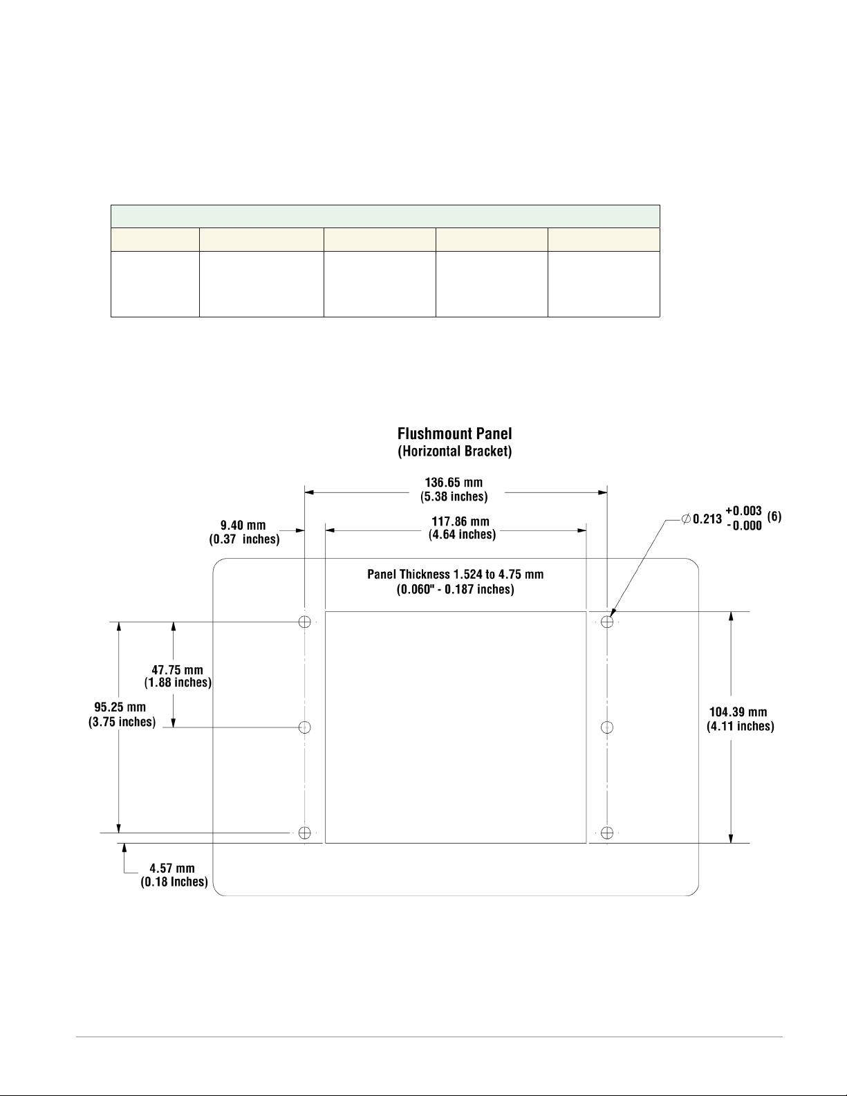
Flush Mounting the Base
1. Fabricate the mounting panel per the ush mount vertical or horizontal panel template
(shown below).
2. Press PEM standoffs (based on panel material) into mounting panel per supplier recom-
mendations.
PEM Standoffs
PEM P/N S0-632-6 Z1 S0S-632-6 S0A-632-6 S04-632-6
Material Steel
(Zinc Plated)
Stainless
Steel Aluminum
Hardened
Stainless
Steel
3. Mount ush mount bracket to back panel with (6) #6-32 screws.
4. Insert the controller through the panel and bracket and lock it in place with the reten-
tion collar as described above.
5. Apply overlay to front panel.
Autres manuels pour F4T
3
Table des matières
Autres manuels Watlow Unité de contrôle


Manuels Unité de contrôle populaires d'autres marques

Festo
Festo Compact Performance CP-FB6-E Manuel de la liste des pièces

Elo TouchSystems
Elo TouchSystems DMS-SA19P-EXTME Manuel utilisateur

JS Automation
JS Automation MPC3034A Manuel utilisateur

JAUDT
JAUDT SW GII 6406 Series Guide rapide

Spektrum
Spektrum Air Module System Manuel utilisateur

BOC Edwards
BOC Edwards Q Series Manuel utilisateur


