Volansys Modular IoT Gateway Manuel d'installation

V1R1 www.volansys.com I Email: business@volansys.com Copyright © 2017 VOLANSYS
Page | 1
MODULAR IOTGATEWAY
HARDWARE USER GUIDE
REVISION V1R1

Modular IoT Gateway User Guide
V1R1 www.volansys.com I Email: business@volansys.com Copyright © 2017 VOLANSYS
Page | 2
Copyright Info
The information contained in this document is the proprietary information of Volansys Technologies Pvt.,
Ltd. The contents are confidential and any disclosure to persons other than the officers, employees,
agents or subcontractors of the owner or licensee of this document, without the prior written consent of
Volansys, is strictly prohibited.
Further, no portion of this document may be reproduced, stored in a retrieval system, or transmitted in
any form or by any means, electronic or mechanical, including photocopying and recording, without the
prior written consent of Volansys, the copyright holder.
Volansys publishes this document without making any warranty as to the content contained herein.
Further Volansys reserves the right to make modifications, additions and deletions to this document due
to typographical errors, inaccurate information, or improvements to products mentioned in the document
at any time and without notice. Such changes will, nevertheless be incorporated into new editions of this
document.

Modular IoT Gateway User Guide
V1R1 www.volansys.com I Email: business@volansys.com Copyright © 2017 VOLANSYS
Page | 3
Table of Contents
1REVISION HISTORY ........................................................................................................................................6
2INTRODUCTION.............................................................................................................................................7
3SPECIFICATION ..............................................................................................................................................9
4CONTENTS OF THE MODULAR GATEWAY KIT .............................................................................................. 22
5SUPPORT..................................................................................................................................................... 24
6APPENDIX-A ................................................................................................................................................ 25

Modular IoT Gateway User Guide
V1R1 www.volansys.com I Email: business@volansys.com Copyright © 2017 VOLANSYS
Page | 4
List of Figures
Figure 1 - Modular Gateway .................................................................................................................... 7
Figure 2 - Modular Gateway With Inbuilt Peripheral ................................................................................8
Figure 3 –Architecture Block Diagram.....................................................................................................9
Figure 4 - SOM Board...............................................................................................................................9
Figure 5 - Base Board............................................................................................................................. 10
Figure 6 - SW01 Settings for Boot Mode Selection ................................................................................. 11
Figure 7 - Resistor Settings for Boot Device Selection (Top Side) ............................................................ 13
Figure 8 - Resistor Settings for Boot Device Selection (Bottom Side) ...................................................... 13
Figure 9 - JTAG Pin Definition................................................................................................................. 15
Figure 10 - Modular Gateway Back Side................................................................................................. 16
Figure 11 - NFC Controller ..................................................................................................................... 17
Figure 12 - MikroBUS Header................................................................................................................. 17
Figure 13- MKW2xD Module with MikroBUS header.............................................................................. 18
Figure 14 - MKW2xD Module................................................................................................................. 18
Figure 15 - MKW41Z Module ................................................................................................................. 19
Figure 16 - JTAG Header for MKW2xD and MKW41z..............................................................................19
Figure 17 - JN5169 Module.................................................................................................................... 20
Figure 18 - JN5179 Module.................................................................................................................... 21

Modular IoT Gateway User Guide
V1R1 www.volansys.com I Email: business@volansys.com Copyright © 2017 VOLANSYS
Page | 5
List of Tables
Table 1 - Revision History ........................................................................................................................6
Table 2 - References ................................................................................................................................6
Table 3 - i.MX6 Ultra Lite SOM DIP SW01 Configuration.........................................................................11
Table 4 - i.MX6 Ultra Lite SOM BOOT Device Configuration.................................................................... 12
Table 5 - Gateway USB Configuration .................................................................................................... 14
Table 6 - Terminal Settings .................................................................................................................... 15
Table 7 - User Interface Switch ..............................................................................................................16
Table 8 - User LED Indications................................................................................................................ 16
Table 9 - J31 - JTAG signal support ........................................................................................................19
Table 10 - JTAG Header for MKW2xD and MKW41z ............................................................................... 19
Table 11 - Modular Gateway Kit Content ............................................................................................... 22
Table 12 - Modular Gateway Unit Contents ........................................................................................... 22
Table 13 - Require Preparation Equipment ............................................................................................ 22
Table 14 - Acronyms & Glossary ............................................................................................................ 25

Modular IoT Gateway User Guide
V1R1 www.volansys.com I Email: business@volansys.com Copyright © 2017 VOLANSYS
Page | 6
1REVISION HISTORY
1.1 Revision History
Rev.
Date
Description
Prepared By
Reviewed By
Approved By
V1R1
22-Dec-17
Initial draft version
VOLANSYS
VOLANSYS
VOLANSYS
Table 1 - Revision History
1.2 References
Documents
Revision
Schematic Design of Volansys’ Base Board
2.05
Schematic Design of Volansys’ SoM
1.05
Datasheet i.MX6UL SOM (IMX6ULCEC)
0.2
Datasheet of MKw2xD
1.0
Datasheet of JN5169 Module
1.1
Quick start Guide of PN7120 NFC Controller Board
1.1
Table 2 - References

Modular IoT Gateway User Guide
V1R1 www.volansys.com I Email: business@volansys.com Copyright © 2017 VOLANSYS
Page | 7
2INTRODUCTION
Volansys presents you a smart modular customizable multi-service reference design of Gateway for
Internet of Things named as –“Modular Gateway”, targeted for multiple use cases in various segments
of IoT such as Smart Home, Buildings and Industries. Core features are its Modular Hardware Design and
Multi-Radio Connectivity (i.e. Wi-Fi, BLE, NFC, Thread and ZigBee).
This document is the hardware user guide for Modular Gateway. This manual provides detail
information about major design peripherals and its usage criteria. It also includes systems setup &
debugging information from hardware systems perspective.
2.1 Board Overview
Figure 1 - Modular Gateway
The Modular Gateway development kit, based on i.MX6UltraLite introduces developers to the i.MX6UL
based SOM board. This gateway will help users to develop and run their IoT based concept using
wireless interfaces like Wi-Fi, BLE, NFC, ZigBee and Thread. It supports Wi-Fi and Ethernet for connection
with cloud.
Modular Gateway supports various hardware module through MikroBUS Header such as Volansys’
KW2xD and KW41Z Thread and other Mikrobus standard supported modules. Also PN7120 base NFC
module and NXP JN5169 ZigBee Module.

Modular IoT Gateway User Guide
V1R1 www.volansys.com I Email: business@volansys.com Copyright © 2017 VOLANSYS
Page | 8
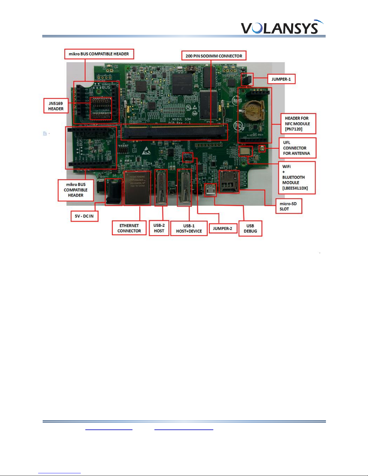
Figure 2 - Modular Gateway With Inbuilt Peripheral
The following features are available with the Modular Gateway development board:
CPU
oi.MX 6UltraLite applications processor with a 528 MHz ARM® Cortex®-A7 core
Memory
o256MB DDR3L SDRAM
o1GB NAND Flash
oMicro SD connector
Communication and Connectivity
o1x 10/100Mbps Ethernet connector
o1x USB 2.0 Host connector
o1x USB 2.0 Host connector (Device mode support)
oMikroBus compatible header to support mikroBUS compatible Volansys’ RF modules (like;
KW41Z, KW2xD) & other MikroBUS’ click modules
oWi-Fi + BT module from Murata
oNFC module using PN7120 controller for commissioning
Other I/O
o1x Debug port via USB micro-B connector
o1x Power LED, 2x Status LED
o1x User Switch (for commissioning), 1x reset Switch
oJTAG connector
Power Supply
oDC Input - 5V/3A

Modular IoT Gateway User Guide
V1R1 www.volansys.com I Email: business@volansys.com Copyright © 2017 VOLANSYS
Page | 9
3SPECIFICATION
Modular Gateway implements a variety of peripheral interfaces through the SODIMM-200 connector to
connect with i.MX6UL based SOM. This section provides detailed information about electrical design &
practical consideration of different peripherals of Modular Gateway.
The architecture block diagram of Modular Gateway board is shown as below:
Figure 3 –Architecture Block Diagram
The overview of Modular Gateway Base and SOM board is shown in following figures,
Figure 4 - SOM Board
Modular IoT Gateway User Guide
V1R1 www.volansys.com I Email: business@volansys.com Copyright © 2017 VOLANSYS
Page | 10
Figure 5 - Base Board
3.1 i.MX6UL
The i.MX 6UltraLite is an ultra-efficient processor family with featuring Freescale’s advanced
implementation of the single ARM Cortex®-A7 core, which operates at speeds of up to 528 MHz.
The device is composed of the following major subsystems:
Single-core ARM Cortex-A7 MPCore™ Platform
32 Kbytes L1 Instruction Cache
32 Kbytes L1 Data Cache
Private Timer and Watchdog
Trust Zone support
Cortex-A7 NEON MPE (Media Processing Engine) Co-processor
3.2 BOOT Mode Configuration
Modular Gateway supports three different boot modes as shown below,
oBoot From Fuses
oSerial Downloader
oInternal Boot
Autres manuels pour Modular IoT Gateway
1
Table des matières
Autres manuels Volansys Porte


Manuels Porte populaires d'autres marques

LST
LST M500RFE-AS Manuel utilisateur

Kinnex
Kinnex Media Gateway Manuel utilisateur

2N Telekomunikace
2N Telekomunikace 2N StarGate Manuel utilisateur

Mitsubishi Heavy Industries
Mitsubishi Heavy Industries Superlink SC-WBGW256 Manuel utilisateur

ZyXEL Communications
ZyXEL Communications ZYWALL2 ET 2WE Manuel utilisateur

Telsey
Telsey CPVA 500 - SIP Manuel utilisateur


