USAVision UA-SNVR Series Manuel utilisateur
Before attempting to connect or operate this product,
please read these instructions carefully and save this manual forfuture use. UVSSNVR-QG-A
Quick Start Guide
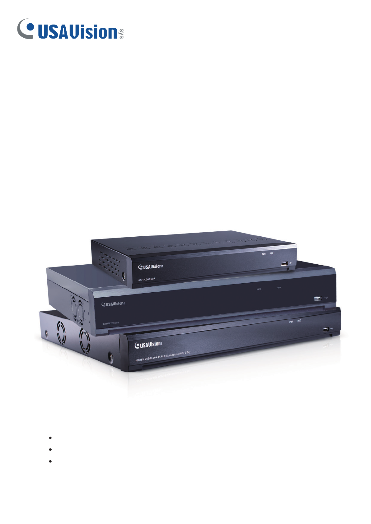
UA-SNVR
UA-SNVR3240-N
UA-SNVR1620-P
UA-SNVRL810-P

© 2022 USAVision, Inc. All rights reserved.
Under the copyright laws, this manual may not be copied, in whole or in part, without
the written consent of USAVision.
Every effort has been made to ensure that the information in this manual is accurate.
USAVision makes no expressed or implied warranty of any kind and assumes no
responsibility for errors or omissions. No liability is assumed for incidental or
consequential damages arising from the use of the information or products contained
herein. Features and specifications are subject to change without notice.
USA Vision Systems Inc.
9301 Irvine Blvd,
Irvine, CA 92618, USA
Tel: +1-949-421-5910
Fax: +1-949-583-152
https://www.geovision.com.tw/us/
October 2022
Scan the following QR codes for product warranty and technical support policy:
[Warranty] [Technical Support Policy]

i
Contents
1. Introduction.........................................................................................................2
1.1 Front View ..............................................................................................................2
1.2 Rear View...............................................................................................................3
1.2.1 UA-SNVR3240-N...................................................................................................... 3
1.2.2 UA-SNVR1620-P...................................................................................................... 4
1.2.3 UA-SNVRL810-P...................................................................................................... 5
2. Installation...........................................................................................................6
2.1 Connection Diagram...............................................................................................6
2.2 HDD Installation......................................................................................................7
2.3 Power Supply Connection.......................................................................................8
3. Getting Started....................................................................................................9
3.1 Start Wizard............................................................................................................9
3.1.1 Start Wizard .............................................................................................................. 9
3.1.2 Connecting IP Cameras............................................................................................ 9
3.2 Getting Started for UA-SNVR3240-N....................................................................12
3.3 Live View Overview ..............................................................................................15
3.3.1 Main Window ..........................................................................................................15
4. Remote Access via Web Client........................................................................17
4.1 Basic System Requirements.................................................................................17
4.2 Looking Up the Dynamic IPAddress.....................................................................18
5. Upgrading Firmware.........................................................................................19
5.1 Upgrading Firmware.............................................................................................19

2
1. Introduction
Welcome to the UA-SNVR Quick Start Guide. In the following sections, you will learn about
the basic installations and configurations. For more details, see UA-SNVR User’s Manual.
Note:The first time you run the NVR, you will be required to set your password immediately
in order to protect your privacy. Please be sure to record your username and password and
save them in a secure place. If you forget your password, you will be unable to log in the
system. For this case, please contact your reseller to reset the password.
1.1 Front View
Item
Description
Power LED
Show constant green when power is supplied.
HDD LED
Show constant red when the HDD is connected.
Flash red when recording or playback is enabled.
USB Port
Connect the supplied mouse or USB flash memory.

3
1.2Rear View
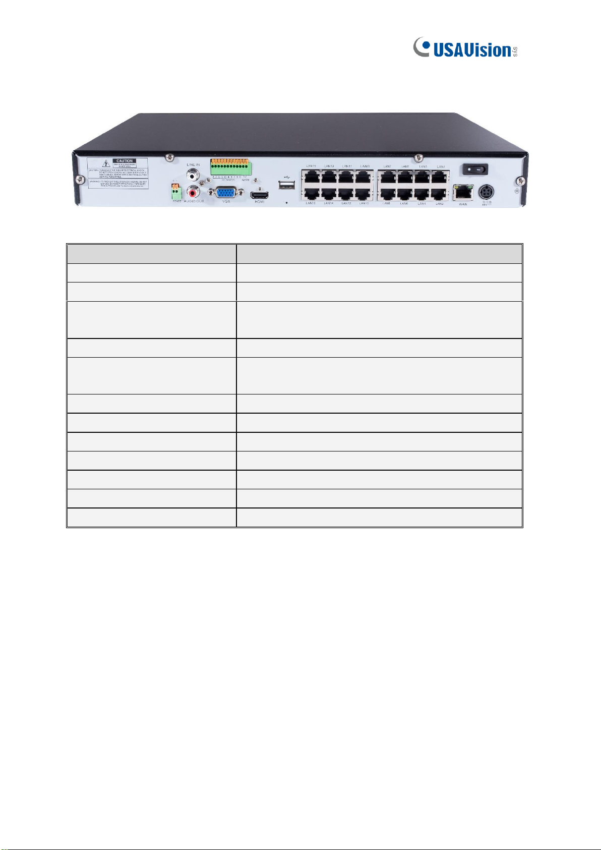
1.2.1 UA-SNVR3240-N
IMPORTANT: WAN and LAN ports are not linked, and the LAN port does not have the
internet access. If you want to connect IP cameras to the LAN port to create a separate and
local network, see 3.2 Getting Started for UA-SNVR3240-N.
Item
Description
Power Switch
Start up and shut down the NVR system.
Power Port
Connect the attached power supply.
USB Port
Connect a USB device, such as USB mouse and USB
flash disk.
Sensor /Alarm / RS-485
Terminal Block
Connect to sensor, alarming devices, and/or RS-485 PTZ
cameras.
Reset
Restore the device to its default settings. The reset hole is
under the USB Port.
HDMI Port
Connect a HDMI-supported monitor.
VGA Port
Connect a VGA monitor, such as PC monitor.
LINE IN
Connect a microphone.
Audio Output
Connect a speaker.
WAN Port
Connect to an external network.
LAN Port
Connect to a router or switch for connecting cameras.
4
1.2.2 UA-SNVR1620-P
Item
Description
Power Switch
Start up and shut down the NVR system.
Power Port
Connect the attached power supply.
USB Port
Connect a USB device, such as USB mouse and USB
flash disk.
Sensor / Alarm Terminal Block
Connect to sensor or alarming devices.
Reset
Restore the device to its default settings. The reset hole
is under the USB Port.
HDMI Port
Connect a HDMI-supported monitor.
VGA Port
Connect a VGA monitor, such as PC monitor.
LINE IN
Connect a microphone.
Audio Output
Connect a speaker.
WAN Port
Connect to an external network.
LAN Port
Connect up to16 cameras, with PoE supply.
RS-485 Terminal Block
Connect to a PTZ camera.

5
1.2.3UA-SNVRL810-P
Item
Description
Power Switch
Start up and shut down the NVR system.
Power Port
Connect the attached power supply.
USB Port
Connect a USB device, such as USB mouse and USB flash
disk.
Reset
Restore the device to its default settings. The reset hole is
under the USB Port.
HDMI Port
Connect a HDMI-supported monitor.
VGA Port
Connect a VGA monitor, such as PC monitor.
Audio Output
Connect a speaker.
WAN Port
Connect to an external network.
LAN Port
Connect up to 8 cameras, with PoE supply.

6
2. Installation
2.1 Connection Diagram
The following diagram is for reference only. The practical connection may be different
depending on the NVR you purchased.
1. You can connect to other IP cameras remotely over the Internet.
2. Connect a CAT.5E or higher RJ45 Ethernet cable for local connectivity. You can connect
to other IP cameras through your local network.
3. Two-way voice conversation with the remote PC.
4. Connect an external hard disk drive to back up files stored on the NVR.
5. Connect the included power cable.
6. Use the USB flash disk for backup, camera, or system upgrade.
7. Connect a RS-485 device such as speed domecamera.
8. Connect an external alarm output device such as siren.
9. Connect external alarm sensors.
10. Connect the video output of the NVR to the TV or monitor via HDMI or VGAconnection.
11. Connect speakers if you want to listen to the live audio or audio playback from the NVR.
12. Connect PoE IP cameras. It may take up to 1 minute for the cameras to start transmitting
video to the NVR.

7
2.2HDD Installation
The number of 3.5" / 2.5" SATA hard drives that the NVR can support varies depending on
the model. The following procedures are for reference only. The practical operation may be
different depending on the NVR you purchased.
Caution: Do not install or remove the hard disk drive while the power is turned on.
a) Connect the data and power cables to the two hard
disk drives and place the hard disk drives on the NVR
case.
b) Carefully flip the NVR case and secure the hard
disk drives to the NVR with the eight (8) screws

8
2.3 Power Supply Connection
Caution: Only use the supplied power adapter that comes with the NVR.
Connect one end ofthe power adapter to the power connector on the back of the NVR. Plug the
other end of the power adapter into the wall outlet.And press the Power Switch toturn on the
power.
Ce manuel convient aux modèles suivants
3
Table des matières
Autres manuels USAVision Matériel réseau


Manuels Matériel réseau populaires d'autres marques

Matrix Switch Corporation
Matrix Switch Corporation MSC-HD161DEL Manuel utilisateur

B&B Electronics
B&B Electronics ZXT9-IO-222R2 Manuel utilisateur

Yudor
Yudor YDS-16 Manuel utilisateur

D-Link
D-Link ShareCenter DNS-320L Manuel utilisateur

Samsung
Samsung ES1642dc Instructions d'utilisation

Honeywell Home
Honeywell Home LTEM-PV Instructions de montage


