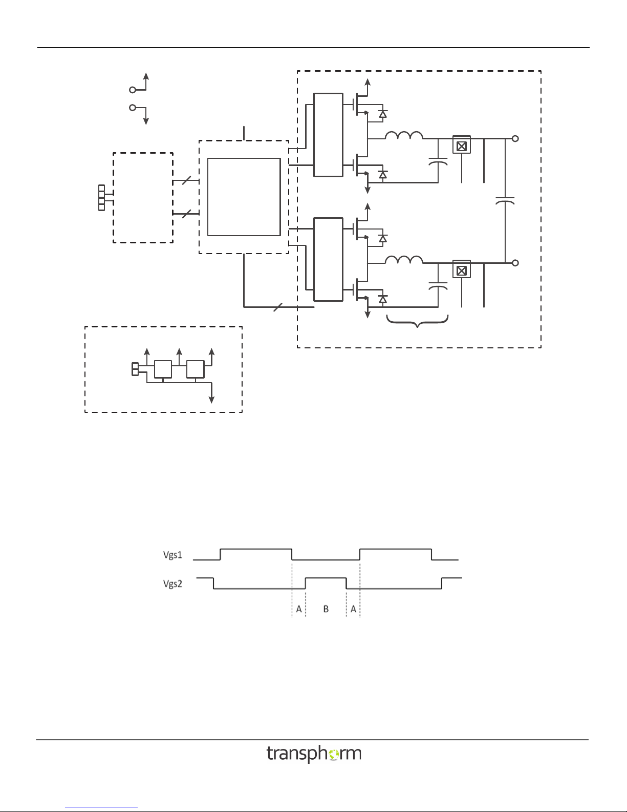
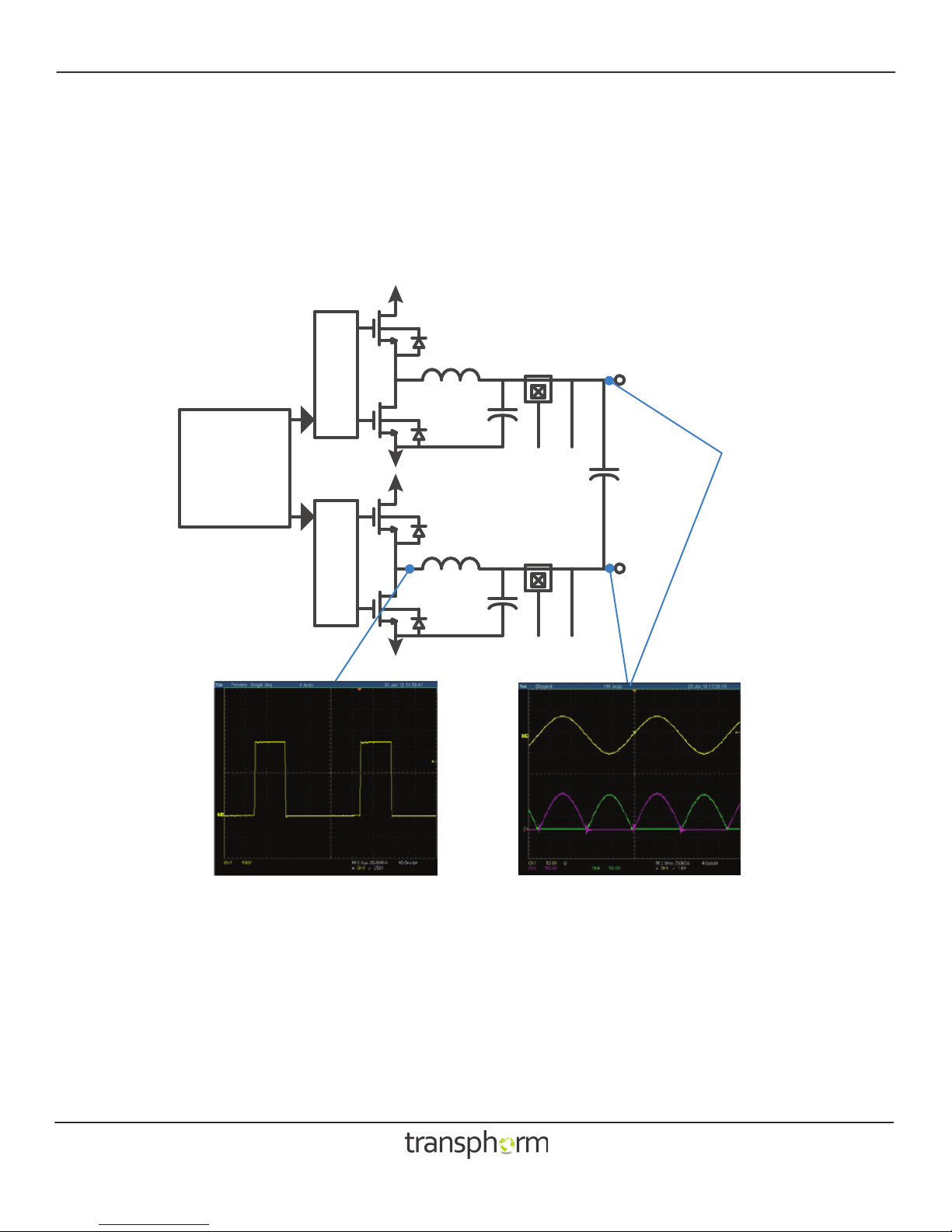
Output filter
A simple LCL filter on the output (L3, L4, C37 and C54 - C57) attenuates the switching frequency, producing a clean sinusoidal
waveform for output connections in terminals J4 and J5. The filter inductors and capacitors used on the demo board were
chosen to provide the optional combination of benefits: low loss, good attenuation of the switching frequency, and small size.
Consult the schematic and/or bill of materials to verify values; but in general, the cutoff frequency will be around 5 - 10kHz to
accommodate 100kHz switching. The inductors have powder cores with relatively low permeability (60-90) and soft saturation
characteristics. The inductors and/or capacitors can be changed to evaluate different filter designs.
Current sensing
Hall sensors U8 and U10 provide linear current feedback to the microcontroller. These signals could be used to control output
power flow, and/or to protect against short circuits. The firmware provided with the kit, however, does not actually make use of
this feedback. Note that these are placed at an intermediate point of the output filter. Refer to the bill of materials to confirm
the sensor part numbers, but typical would be the Allegro ACS712-20A sensor, which has a ±20A range (100mV/A). These parts
are pin compatible with a ±5A and ±30A versions of ACS712, should higher or lower ranges be desired. Note also that resistor
dividers scale the 5V outputs for the 3V range of the A/D.
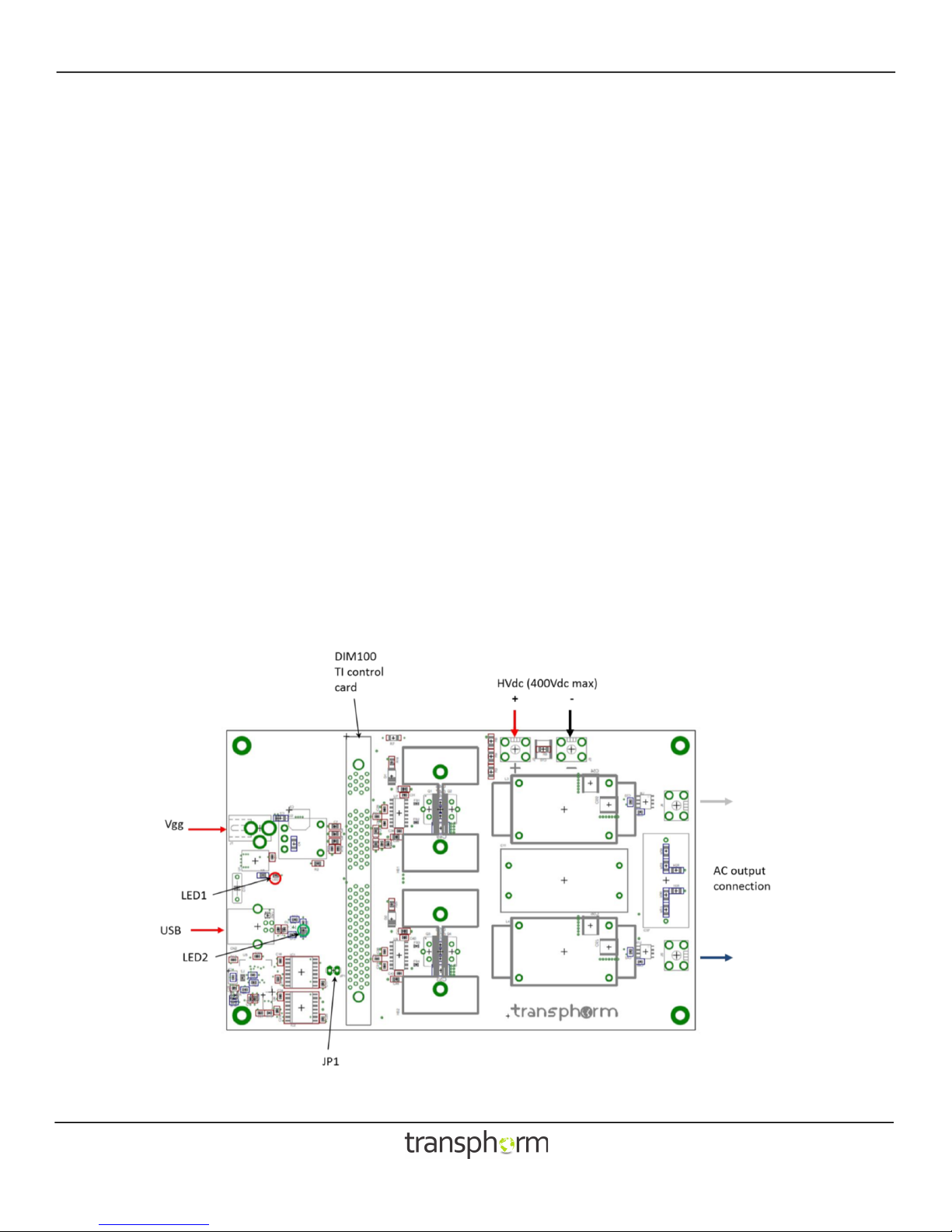
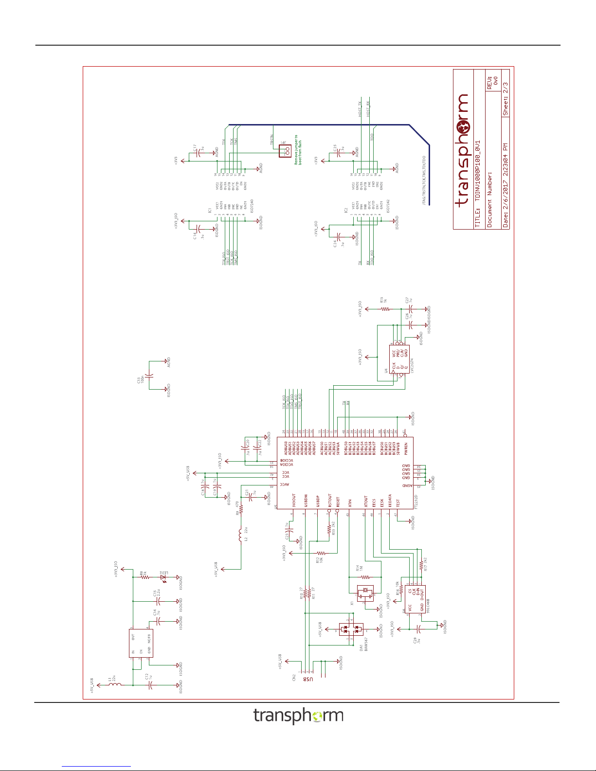
Communication
Communication between the microcontroller and a computer is accomplished with a standard USB cable. The isolated USB
interface enables simultaneous operation of two physical ports to the microcontroller: a JTAG port for debug and loading of
firmware, and a UART for communication with a host application.
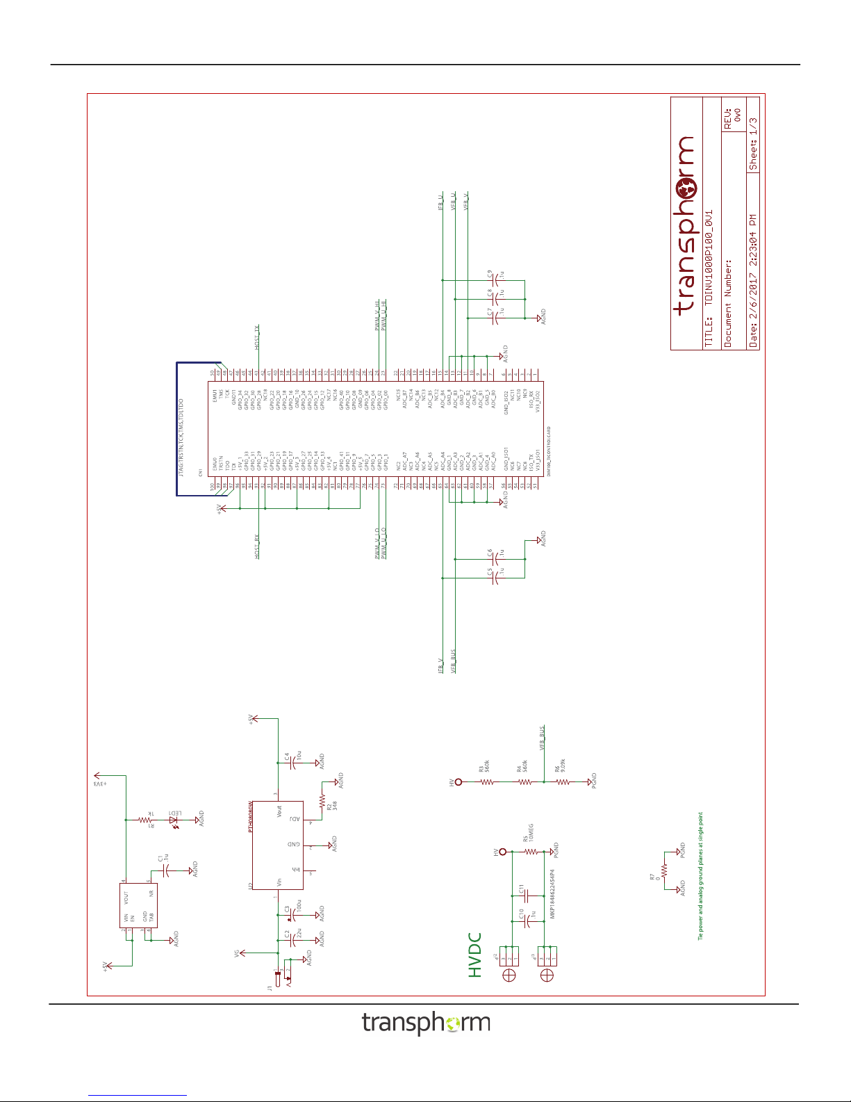
Control card
The microcontroller resides on a removable card, which inserts in a DIM100 socket on the inverter PCB. The socket can accept
many of the C2000 series control cards from Texas Instruments. The TMDSCNCD28035 Piccolo control card supplied with the
kit provides capability to experiment with a wide variety of modulation and control algorithms. It comes loaded with firmware to
allow immediate, out-of-the-box, operation. Should the user wish to use an alternative microcontroller family, an appropriate
control card can be designed to insert into the DIM100 socket.
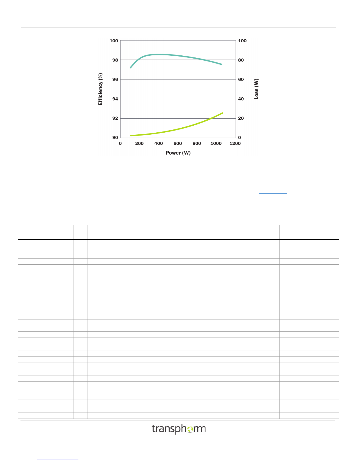
Heat sink
The two TO-220 GaN transistors on each half-bridge are mounted on a common heat sink. The heatsink is adequate for 1000W
operation WITHOUT forced air flow. Even higher efficiency at high power may be achieved by minimizing the temperature rise.
This may be accomplished with forced airflow. Alternately the heatsinks could be replaced with larger and more effective ones.
Connections
Power for the AC output is derived from the high voltage DC input. This will typically be a DC power supply with output voltage up
to 400VDC. A 22µF, low ESR, film capacitor is provided as a bypass capacitor for the high voltage supply, along with several
smaller value ceramic capacitors in parallel. This is not intended to provide significant energy storage, but to provide high
frequency bypassing. It is assumed that the power supply or preceding DC-DC stage contains adequate output capacitance.
The control, communication, and gate-drive circuits are all powered from a single 9V input (VGG). A wall-plug adaptor is provided.