Touchboards PFDM2 Manuel utilisateur


www.mounts.com | North America 800.368.9700 | International +1-714-632-7100
Included components
Required for installation
PFDM2
Installation Guide
Installationsanleitung, Guía de Instalacíon, Guida de Installazione, Guide d’Installation, Installatie gids
Maximum Flat Panel Weight:
100 lb. / 45.35 kg.
x4
M4 x 12mm
screw
x4
M4 x 16mm
screw
x4
M4 x 25mm
screw
x4
M6 x 12mm
screw
x4
M6 x 16mm
screw
x4
M6 x 25mm
screw
x4
M8 x 16mm
screw
x4
M8 x 25mm
screw
x4
5/16” x 3”
Lag Bolts
x4
Washers
x4
Universal 3
HoleWasher
x8
Universal
Spacer
x1
Depth Measuring
Straw x1
Lock-it Barrel
Page 2
Pencil Level
1/4” Drill Bit for
Wood Stud
Electronic Stud Finder
Socket Wrench Phillips Tip Screwdriver Tape Measure
Hand Held Drill
Protective Eyewear
1/2” Socket
O
N
x1
Wall Plate
x2
Mounting Brackets

1
PFDM2
Installation Guide
Installationsanleitung, Guía de Instalacíon, Guida de Installazione, Guide d’Installation, Installatie gids
Page 3
Introduction
Directional Mounting Arrow
The Directional Mounting Arrow stamped
into the top of the PFDM2 wall mount
indicates which edge is the top.
Mounting Safety
Two people are recommended for the
installation of this mount.
www.mounts.com | North America 800.368.9700 | International +1-714-632-7100
XX
You must secure the wall plate to two (2)
wall studs with a minimum of four (4) lag
bolts (2 lag bolts for each stud found).
Use a stud nder to determine the exact
center of wall studs in the vicinity of the wall
plate.
Use a pencil to mark the exact center of each
of the wall studs.

PFDM2
Installation Guide
Installationsanleitung, Guía de Instalacíon, Guida de Installazione, Guide d’Installation, Installatie gids
www.mounts.com | North America 800.368.9700 | International +1-714-632-7100
Page 4
3
2Two people are recommended for this step; one
person to level the wall plate and another person
to mark the wall stud location.
Place the wall plate against the wall in the desired
viewing location.
Adjust the wall plate to align the mount slots in the
wall plate with the center of the wall studs.
Level the wall plate.
Use a pencil to mark the upper right mounting
location along the center of the wall stud.
Drill a “pilot hole” in the center of the upper right mark
using a 1/4” drill bit and power drill.
Only use a 1/4” drill bit when drilling the pilot
holes.

4 Place the wall plate against the wall and align it with
the pilot hole.
Insert one (1) 5/16” x 3″ lag bolt and one (1) 5/16”
washer into the upper right mounting hole and
tighten using a socket wrench and 1/2” socket.
Do not overtighten the lag bolt.
5
www.mounts.com | North America 800.368.9700 | International +1-714-632-7100 Page 5
Level the wall plate.
Use a pencil to mark the remaining three (3)
mounting locations along the center of each wall
stud.
PFDM2
Installation Guide
Installationsanleitung, Guía de Instalacíon, Guida de Installazione, Guide d’Installation, Installatie gids
PFDM2
www.mounts.com | North America 800.368.9700 | International +1-714-632-7100
Page 6
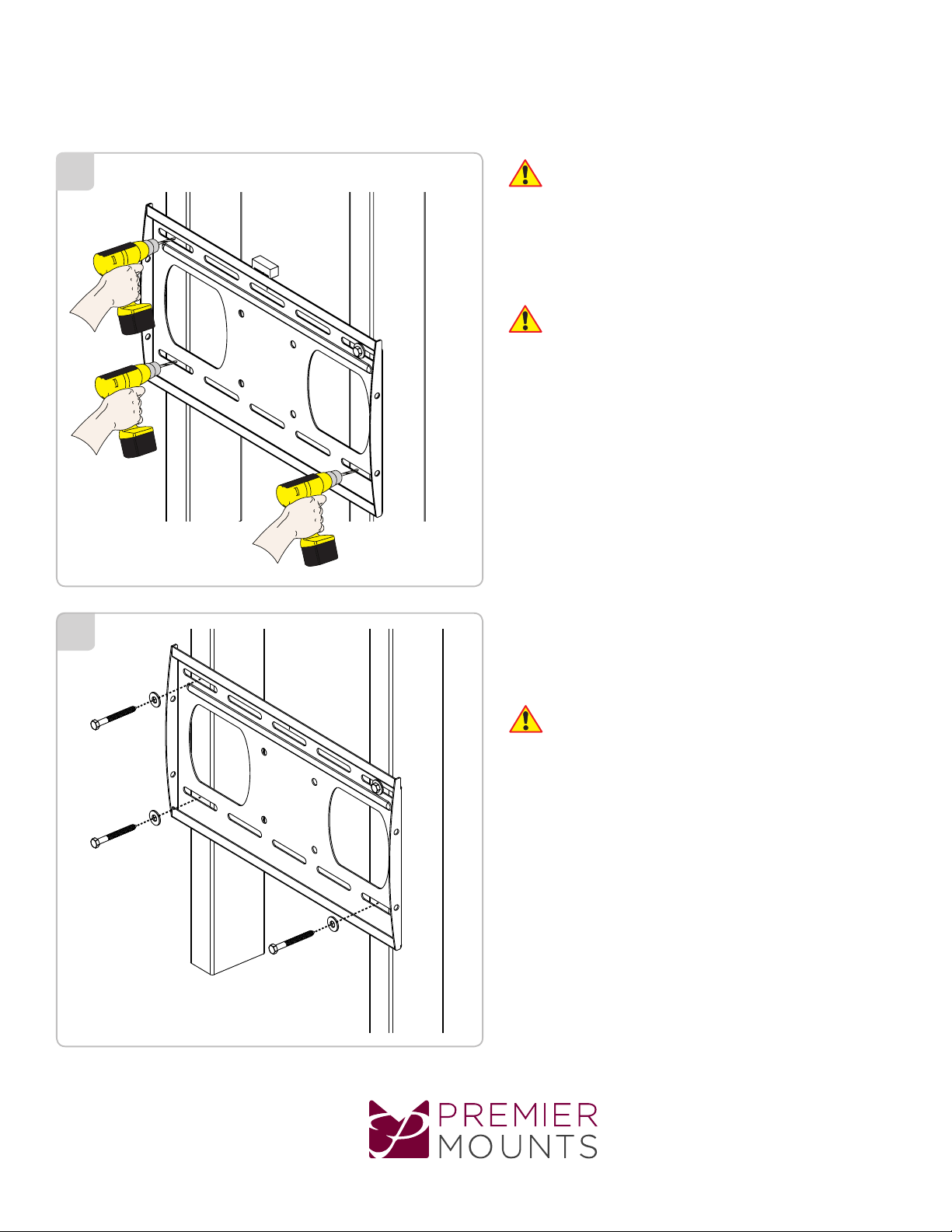
7
6Two people are recommended for this step; one
person to level the wall plate and another person
to drill the pilot holes.
Drill a “pilot hole” in the center of each of the marks with
a power drill and a 1/4” drill bit.
Only use 1/4” drill bit when drilling the pilot holes.
Insert one (1) 5/16” x 3” lag bolt and one (1) 5/16”
washer into each pilot hole.
Tighten all lag bolts using a socket wrench and 1/2”
socket.
Do not overtighten the lag bolts when attaching
the mount to the wall. Improper installation may
result in personal injury or property damage.
Proceed to the “Installing the Mounting Bracket”
section.
Installation Guide
Installationsanleitung, Guía de Instalacíon, Guida de Installazione, Guide d’Installation, Installatie gids

www.mounts.com | North America 800.368.9700 | International +1-714-632-7100 Page 7
Installing the Mounting Bracket
Small Straw or Toothpick
Small Straw
or Toothpick
Small Straw
or Toothpick
Marking the 1/8”
Allowance
Depth Plus 1/8” Allowance
Mark
Depth Plus 1/8” Allowance
Mark
Insert a small straw or toothpick into the threaded
inserts found on the back of the at panel.
Use a pencil to mark the depth of the threaded
insert on the small straw or toothpick.
Mark the straw or toothpick 1/8” above the depth of
the threaded insert, as shown in Figure 1.
Insert the small straw or toothpick into the remaining
threaded inserts to compare and verify their depth
using the straw or toothpick’s 1/8” allowance mark.
Locate the correct diameter screw for the threaded
insert.
If the screw you selected is longer than the 1/8”
allowance mark on the small straw or toothpick,
as shown in Figure 2 and Figure 3, do not use
this screw. The screw length must not bypass the
mark.
Test each size of the screws provided.
The correct screws should thread easily into the
mounting point and not pull out when tension is
applied.
Proceed to the “Universal Washer Installation”
section.
Selecting the Mounting Hardware
PFDM2
Installation Guide
Installationsanleitung, Guía de Instalacíon, Guida de Installazione, Guide d’Installation, Installatie gids

PFDM2
Installation Guide
Installationsanleitung, Guía de Instalacíon, Guida de Installazione, Guide d’Installation, Installatie gids
www.mounts.com | North America 800.368.9700 | International +1-714-632-7100
Page 8
Premier Mounts’ Universal Washers are designed to
accommodate the various M4, M5, M6 and M8 hole
sizes required by at panels.
Do not place excessive pressure on the back of
the at panel, as this may damage your at panel.
The Universal Washer must be installed between
the head of the mounting screw and the mounting
bracket as shown.
Does your at panel have:
●Recessed mount points?
●Uneven mount points?
●A curved back?
●Any obstruction near the mount point?
If Yes, you must install Universal Spacers. Remove the
mounting brackets, Universal Washers, and mounting
screws from the back of the at panel. Proceed to the
“Universal Spacer Installation” section.
If No, skip to the “Attaching the Mounting Bracket
to the Flat Panel” section.
Premier Mounts’ Universal Spacers allow you to
attach the mounting bracket to at panels which have
recessed or uneven mount points. Each Universal
Spacer adds ¼˝ to the distance between the mounting
bracket and your at panel.
The Universal Spacers must be stacked and
oriented as shown.
The Universal Spacers must only be installed
between the mounting bracket and your at panel.
The Universal Spacers will t M4, M5, M6 and M8
screw sizes.
Proceed to the “Attaching the Mounting Bracket to
the Flat Panel” section.
1˝ ¼˝
Universal Washer Installation
Universal Spacer Installation
Flat Panel
Universal Washer
Universal Spacer
Mounting Bracket
Mount Point
Mounting Screw

www.mounts.com | North America 800.368.9700 | International +1-714-632-7100 Page 9
PFDM2
Installation Guide
Installationsanleitung, Guía de Instalacíon, Guida de Installazione, Guide d’Installation, Installatie gids
Leveling Screw Installation
You must install the leveling screws before you
attach the mounting bracket to the back of the at
panel. The leveling screws consists of two (2) M6
x 75mm screws.
Thread one (1) leveling screw into the top mounting
hole on each of the mounting brackets. Make sure the
leveling screw is securely threaded into the mounting
tab before proceeding.
Do not thread the leveling screw any further once
it is even with the mounting tab. Threading the
leveling screw any further will prevent you from
safely attaching the at panel to the wall plate.
Locking Screw Installation
You must install the locking screws before you
attach the mounting bracket to the back of the at
panel. The locking screws consists of two (2) M6 x
75mm screws.
Thread one (1) locking screw into the bottom mounting
hole on each of the mounting brackets. Make sure the
locking screw is securely threaded into the mounting tab
before proceeding.
Do not thread the locking screw any further once
it is even with the mounting tab. Threading the
locking screw any further will prevent you from
safely attaching the at panel to the wall plate.
Proceed to the “Lock-It™Security Barrel
Installation” section.
Locking Screw
Correctly Threaded
Locking Screw
Threaded Too Far
Leveling Screw
Correctly Threaded
Leveling Screw
Threaded Too Far
Lock and Leveling Screw Installation

PFDM2
Installation Guide
Installationsanleitung, Guía de Instalacíon, Guida de Installazione, Guide d’Installation, Installatie gids
www.mounts.com | North America 800.368.9700 | International +1-714-632-7100
Page 10
Attaching the Mounting Bracket to the Flat Panel
Do not overtighten the locking screw.
Please read the following directions to install the
security barrel:
Remove the locking screw from the mounting
bracket.
Place the locking screw into and through the
security barrel (see illustration below).
Re-insert the locking screw and security barrel into
the mounting bracket.
Optional security congurations include:
- PCB-CSL1 (sold separately)
- Padlock (Combination or Keyed; commercially
available)
Lock-It™ Security
Barrel
Locking Screw
Do not thread the locking screw any further once
it is even with the mounting tab (see illustration to
the right). Threading the locking screw any further
will prevent you from safely attaching the at
panel to the wall plate.
Mounting Tab
Ultilizing the Security Barrel
This section presumes that you have read and
understood these sections:
●Selecting the Proper Mounting Hardware
●Universal Washer Installation
●Universal Spacer Installation
Place your at panel screen-side down on a soft, at
surface.
Identify the number and location of the thread
inserts on the back of your at panel.
Aligning the holes on each mounting bracket with
the thread inserts on the back of your at panel.
Secure each mounting bracket to your at panel by
inserting a minimum of two (2) screws per bracket.
Do not overtighten the mounting hardware.
Table des matières
Autres manuels Touchboards Support TV


