tornos SAS 16.6 Manuel utilisateur

SAS 16.6
INSTRUCTION MANUAL
ENGLISH VERSION TRANSLATED FROM THE ORIGINAL VERSION
TORNOS SA CH-2740 MOUTIER
http://www.tornos.ch
Ref. : 300801_en – Printed in Switzerland - Copyright © 1999-2012
Caution!
Before handling the machine,
all users must read the and pay particular attention to the
"SAFETY INSTRUCTIONS" !
Keep this document for future reference.


Instruction manual - SAS 16.6
300801_en - 12/12
I. Identification
I.1. Document
Instruction manual SAS 16.6
No 300801_en
Version manager
Version Date Description
10/12 19/10/2012 First edition

300801_en - 12/12
Instruction manual - SAS 16.6
I.2. Manufacturer
TORNOS SA
Rue Industrielle 111
CH-2740 MOUTIER / SWITZERLAND
Tel. +41 (0)32 494 44 44
Fax +41 (0)32 494 49 03
www.tornos.ch
I.3. Products
SAS 16.6

Instruction manual - SAS 16.6
300801_en - 12/12
Source suvaPro
Behaviour in the event of an emergency
1. Keep calm
2. Think
3. Act Raise the alarm Ambulance
Police
Fire brigade
Poisoning
Doctor
Hospital
Who? Person raising the alarm.
What? What happened?
Where? Place, street, number, access, floor, etc.
How many? Number of people involved.
Other Particular dangers, dangerous materials, etc.
Accident 1. Secure the dangerous area.
2. Raise the alarm.
3. Give first aid.
4. Inform ambulance staff.
Position(s) of first aid box:
Fire 1. Notify the fire brigade.
2. Find shelter for yourself and others.
3. Close window(s) and door(s).
4. Inform the fire brigade staff.
5. Put the fire out.
Evacuation 1. Notify the people in danger and evacuate them.
2. Leave the premises using the stairs.
3. Go to the assembly point.
Assembly point(s):
Person in charge of keeping the emergency numbers, first aid boxes and training up-to-date:
Mandatory!
Apply the regulations in force in your company. If there are no regulations, you can adapt the
above example to your country’s legislation and to the specific needs of your company.

300801_en - 12/12
Instruction manual - SAS 16.6

Instruction manual - SAS 16.6
300801_en - 12/12
TABLE OF CONTENTS
1 Installation conditions.............................................................................. 1-1
1.1 Machine identification....................................................................................1-1
1.2 Machine dimensions.......................................................................................1-2
1.2.1 Technical features and dimensions...................................................................... 1-2
1.2.2 Machine dimensions with the unprotected reel.................................................. 1-3
1.2.3 Machine dimensions with the unprotected with reel and protection............... 1-4
1.2.4 Machine dimensions with the unprotected sediment tank................................ 1-5
1.3 Safety clearance.............................................................................................1-6
1.3.1 Peripheral devices.................................................................................................. 1-6
1.4 Conditions of use.............................................................................................1-7
1.4.1 Respecting the environment ................................................................................. 1-7
1.4.2 Quality of floors....................................................................................................... 1-7
1.4.3 Operating environment.......................................................................................... 1-8
1.4.3.1 Temperature and ambient humidity...............................................................................1-8
1.4.3.2 Noise ..................................................................................................................................1-8
1.4.4 Air extraction specifications.................................................................................. 1-9
1.4.4.1 Minimum room volume....................................................................................................1-9
1.4.4.2 Ventilation of premises.....................................................................................................1-9
1.5 Energy supply connection specifications...................................................1-10
1.5.1 Electrical connection ........................................................................................... 1-10
1.5.2 Installation characteristics................................................................................... 1-11
1.5.3 Pneumatic connection......................................................................................... 1-13
1.6 Guard opening/closing................................................................................1-15
1.7 Consumable filling ........................................................................................1-17
1.7.1 Lubricants .............................................................................................................. 1-17
1.7.1.1 Lubricant equivalence table .........................................................................................1-17
1.7.1.2 Lubricant equivalence table: greases..........................................................................1-17
1.7.1.3 Restrictions.......................................................................................................................1-18
2 Installation................................................................................................. 2-1
2.1 Work environment (specific to the installation)............................................2-2
2.1.1 Order and cleanliness............................................................................................ 2-2
2.2 Unpacking........................................................................................................2-4
2.2.1 Removal of the transport straps............................................................................. 2-4
2.3 Installation........................................................................................................2-5
2.4 Cleaning...........................................................................................................2-5
2.5 Alignment of the bolt-making machine / bar feeder .................................2-6
2.6 Oil recovery tank.............................................................................................2-8
2.7 Connecting the energy supplies ...................................................................2-9
2.7.1 Electrical connection ............................................................................................. 2-9
2.7.1.1 Connections between the basic machine and the electric cabinet........................2-10
2.7.1.2 Connection to the local mains......................................................................................2-11
2.7.1.3 Connection via an autotransformer..............................................................................2-12
2.7.2 Peripheral options device connection............................................................... 2-13
2.7.3 Pneumatic connection......................................................................................... 2-14

300801_en - 12/12
0. - Instruction manual - SAS 16.6
0-6
2.8 Topping up liquids......................................................................................... 2-15
2.8.1 Cutting liquid tank ................................................................................................ 2-15
2.8.2 Oil tank................................................................................................................... 2-16
2.9 Preparation of the machine for movement................................................ 2-17
2.9.1 Disconnecting power sources............................................................................. 2-17
2.9.1.1 Electrical power supply .................................................................................................2-17
2.9.1.2 Pneumatic power supply...............................................................................................2-18
2.9.2 Emptying liquids.................................................................................................... 2-18
2.9.2.1 Cutting liquid...................................................................................................................2-18
2.9.2.2 Greasing liquid ...............................................................................................................2-18
2.9.2.3 Machine cleaning..........................................................................................................2-18
2.10 Moving the machine .................................................................................... 2-19
2.10.1 Lifting the machine............................................................................................... 2-19
Instruction manual - SAS 16.6 - 1. Installation conditions
300801_en - 12/12 1-1
1. Installation conditions
For unpacking and moving the machine, see the document Transport sheet.
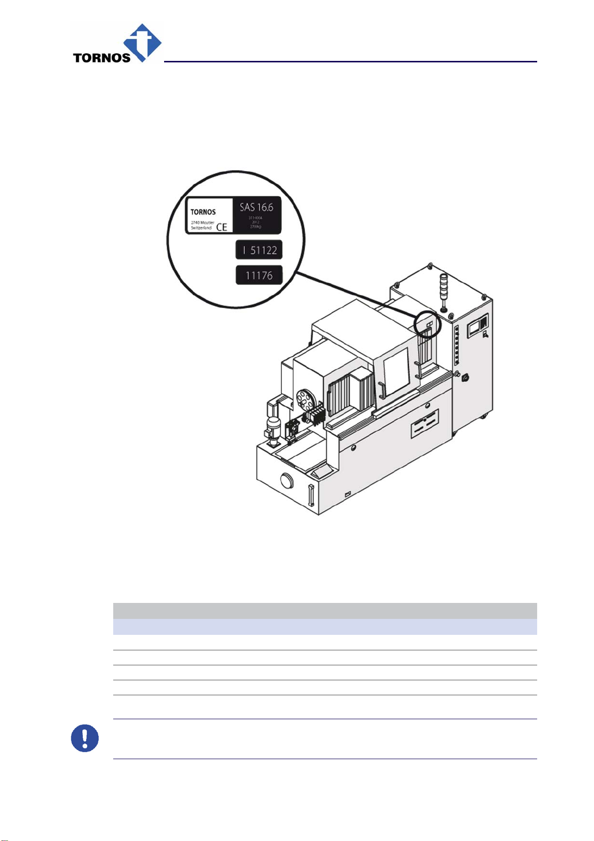
1.1. Machine identification
Fig. 1
The warning plate contains the following information:
Location of parts
Rep. Description
(1) Machine type
(2) Serial number
(3) Machine identification number
(4) Year of manufacture
Mandatory!
The serial number must be quoted for all contacts with TORNOS SA departments.

300801_en - 12/12
1. Installation conditions - Instruction manual - SAS 16.6
1-2
1.2. Machine dimensions
1.2.1. Technical features and dimensions
Name Unit Value
Number of spindles - 6
Maximum round bar release (diameter) mm 16
Maximum hexagonal bar release (s/flat) mm 13
Maximum square bar release mm 11
Spindle speed (3 ranges according to stress)
Range 1 – Ratio R1 rpm 800 to 2000
Range 2 – Ratio R2 rpm 800 to 4000
Range 3 – Ratio R3 rpm 800 to 8000
Production range p/min 3 to 75
Accelerated run programmable up to rpm 65
Maximum length feeder with standard cams mm 63
Maximum length parts with standard cams mm 52
Maximum length feeder with LP* cams mm 85
Maximum length parts with LP* cams mm 75
*The use of LP cams limits production to 60 p/min and
spindle speed to 6000 rpm
Number of transverse sliders - 6
Run of transverse sliders mm 20
Number of available independent feeders - 4
Normal run for independent feeders mm 45
Central slider run mm 50
Drive motor for spindles
Constant torque up to 4,000 rpm) Nm 47.7
Constant power from 1500 rpm (50 % ED) kW 7.5
Camshaft drive motor
Rated torque Nm 5.9
Maximum speed rpm 3,000
Coolant pump motor (50Hz)
Speed rpm 1500
Power kW 2.2
Coolant pump capacity (to 50Hz) l/min 95
Outer dimensions (see figures 2 to 7)
Machine and command cabinet, leng. mm 2962
Machine with 3 m long guidebars. mm 5049
Width (at guard) mm 1100
Height on the spraying guard mm 1615
Height at signal lamp mm 1962
Weight of the machine alone, approx. kg 2,700
Weight of electrical command cabinet, approx. kg 270
Table des matières
Autres manuels tornos Tour

tornos
tornos DECO 13a Manuel utilisateur

tornos
tornos EvoDECO 10/10 Manuel utilisateur

tornos
tornos MultiDeco 26/6 Manuel utilisateur

tornos
tornos DECO 20/10 PTO Manuel du propriétaire

tornos
tornos BS 20.8 Manuel utilisateur

tornos
tornos DECO 7e Manuel utilisateur

tornos
tornos MultiDeco Series Instructions d'installation


