Tiso CENTURION-M TWIN Manuel utilisateur

“TiSO-PRODUCTION” LTD
SERVO-OPERATED TRIPOD TURNSTILE
CENTURION-M TWIN
BASTION-M TWIN
TWIX-M TWIN
OPERATION MANUAL
2019

2
CONTENTS
INTRODUCTION.........................................................................................................................................3
WARNINGS TO THE CUSTOMER ...........................................................................................................4
ON SAFE OPERATION OF THE TURNSTILE.........................................................................................4
1. DESCRIPTION AND OPERATION........................................................................................................5
1.1. General Information and Purpose..............................................................................................5
1.2 Specifications...................................................................................................................................6
1.3 Configuration and Scope of Delivery ..............................................................................................6
1.4 Design and operation ......................................................................................................................9
1.5 Instrumentation, tools and accessories...........................................................................................12
1.6 Description and operation of controllers as components of the turnstile.......................................13
2 INTENDED USE.....................................................................................................................................22
2.1 Operation limitations .....................................................................................................................22
2.2 Layout and installation...................................................................................................................22
2.3 Preparation for use.........................................................................................................................28
2.4 Contingency actions.......................................................................................................................29
3 MAINTENANCE ....................................................................................................................................29
3.1 General guidelines .........................................................................................................................29
3.2 Safety Measures............................................................................................................................30
3.3 Maintenance procedure.................................................................................................................30
4 ROUTINE MAINTENANCE..................................................................................................................31
4.1 General guidelines ........................................................................................................................31
4.2 Possible malfunctions ....................................................................................................................31
4.3 Post repair checkout.......................................................................................................................33
5 TRANSPORTATION AND STORAGE.................................................................................................33
5.1 Turnstile storage.............................................................................................................................33
5.2 Turnstile transportation..................................................................................................................33
6 DISPOSAL...............................................................................................................................................34
7 MANUFACTURER'S WARRANTY AND TERMS OF WARRANTY MEAINTENANCE...............34
Annex А Design, overall and installation dimensions of the " СENTURION-М TWIN " type turnstile...36
Continued Annex А Design, overall and installation dimensions of the turnstile «BASTION-M TWIN»
.....................................................................................................................................................................37
Continued Annex А Design, overall and installation dimensions of the turnstile «TWIX-M TWIN».......38
Annex B Control panel and connection diagram ........................................................................................39
Annex C Servo-operated tripod turnstile wiring diagram...........................................................................41
Annex D.1 Wiring diagram of the turnstile connection to access control system (ACS) in pulse mode....42
Annex D.2 Wiring diagram of the turnstile connection to access control system (ACS) in hold mode.....43
Annex D.3 Wiring diagram of the turnstile connection to fire alarm system (FAS) ..................................44
Annex D.4 Wiring diagram of the turnstile connection to fire alarm system (FAS) ..................................45
Annex D.5 Wiring diagram of the turnstile connection to control panel....................................................46

3
INTRODUCTION
This Operation Manual (hereinafter referred to as OM) covers the servo-operated
turnstile (hereinafter referred to as the "turnstile"). The Operation Manual contains information
about design, specifications, installation for proper operation and maintenance of the turnstile.
This Operation Manual is prepared in compliance with the specification requirements ТУ
У 28.9-32421280-005:2018.
The turnstile shall be serviced only by the qualified staff having the relevant class of
permit to work with electrical facilities with voltage up to 1000 V and scrutinizing this Operation
Manual, obtaining safety instructions and trained for operation and maintenance of the turnstile.
Reliability and durability of the turnstile operation is provided with observation of modes
and conditions of transportation, storage, installation and operation. So, fulfillment of all
requirements specified in this document is mandatory.
Due to regular improvement of the product its design can be modified without
degradation of the product features and quality not covered by this Operation Manual.
Depending on the turnstile purpose and design features, the following pattern of reference
designation is accepted:
T3. XXX. X X. X
турникет полуростовой
Т3
1
Single
2
Double -
TCC
Servo-operated
О
without antipanic device
solid body tripod
Е
with mechanical antipanic
device
(3 barrier rods)
М
with electromechanical
antipanic device
TCY
Servo-operated
one-piece elongated body
tripod (3 barrier rods)
S
Brushed stainless steel
P
Polished stainless steel
K
Painted body
TCG
Servo-operated
head body tripod
(3 barrier rods)
TYK
Servo-operated
corner body tripod
(3 barrier rods)
The tripod type turnstile reference designation is given in Table 1.
Table 1
Name
Code
Designation
CENTURION-М TWIN
T3.TCC.ХE.2
AUIA.095-10-X2 OM
BASTION-М TWIN
T3.TCY.ХE.2
AUIA.097-10- X2 OM
TWIX-М TWIN
T3.TYK.ХE.2
AUIA.137-10-X2 OM
Example of reference designation of the servo-operated turnstile with solid body of
brushed stainless steel when the turnstile T3.ТСC.SE.2 ТY Y 31.6-32421280-005:2018 is
ordered

4
WARNINGS TO THE CUSTOMER
ON SAFE OPERATION OF THE TURNSTILE
These warnings are designed for ensuring of safety during operation of the turnstile to
prevent violation of safety characteristics by improper installation or operation. These warnings
are aimed at drawing attention of the customer to safety problems.
GENERAL WARNINGS
The Operation Manual is an integral part of the product and it shall be handed over to the
customer. The OM shall be kept for future use and consulted for clarifications if required. If the
turnstile is resold, handed over to another owner or transported to another place, make sure that
the OM is enclosed to the turnstile to be used by new owner and/or maintenance staff during
installation and/or operation.
Safety measures and requirements specified in this OM must be observed:
−the turnstile must be connected to ground loop prior to operation;
–the turnstile to be connected to AC network with parameters specified in paragraph 1.2
"Specifications";
–inspection, adjustment and repair should be performed only after the turnstile is
deenergized.
After purchasing of the turnstile it should be unpacked and its integrity should be checked.
In case of doubt in integrity of the turnstile it should not be used and the customer should refer to
the supplier or to the manufacturer.
Packing accessories (wooden pallet, nails, clips, polyethylene bags, cardboard etc.) as
potential sources of hazard must be removed to unacceptable place prior to proper use of the
turnstile.
As electric shock protection device the turnstile is related to 01 protection class according
to GOST (State Standard) 12.2.007.0-75 and is not intended for operation in explosive and fire-
hazardous areas by the "Rules for design of electrical installations". Using of the turnstile for
unintended purpose, improper installation, nonobservance of conditions of transportation,
storage, installation and operation, specified by this OM, may result in damage to people,
animals or property for which the manufacturer is not responsible.

5
1. DESCRIPTION AND OPERATION
1.1. General Information and Purpose.
1.1.1 Turnstile purpose:
The turnstile is designed for arrangement of individual pedestrian access at access points of
industrial enterprises, banks, stadiums, administrative facilities etc. driven by control signals of
access control system (from keypad, proximity card readers) or manually (from wire control
panel).
The turnstile traffic flow capacity without personal identification is at least 25 persons per
minute.
1.1.2 The turnstile dimensions and weight correspond to the values specified in Table 2.
Table 2
Designation of
modification
Dimensions, mm
Pedestal size,
(LxW)mm
Maximum
weight, kg
Н
L
В
T3.TCC.XE.2
1000
793
1580
324х550
50*
T3.TCY.ХE.2
1000
793
1530
524х500
55*
T3.TYK.ХE.2
1000
1000
1520
1004х490
84*
1.1.3 The operation condition parameters according to GOST 15150-69 are specified in
Table 3.
Table 3
Operation conditions
For climatic
modification
Parameter value
Ambient temperature
NF4
+1°С to +40°С
Relative humidity
80 % at 20 ºС
Ambient temperature allowable
pressure
84 to 106,7kPa
Transportation temperature range
- 40°С to + 50°С
Storage temperature range
+ 5°С to + 40°С
Group of mechanical application
L3
Altitude above sea level
up to 2000 m
Environment
Explosion-proof, does not contain
current-conducting dust, aggressive
gases and vapours in concentration
destroying isolation and metals,
disturbing normal operation of the
equipment installed in turnstiles
Installation site
In enclosed spaces in the absence of
direct impact of precipitations and
solar radiation
Operating position
Vertical, deviation from vertical
position no more than 1º to any side
is tolerated

6
Fig.1. –Tripod turnstile scope of delivery
1.1.4 Reliability indices:
mean time to repair (without delivery time of spare parts, tools and accessories) – at
most 6 hours;
mean time to failure – at least 1 500 000 accesses;
mean service life between overhauls – at least 10 years
1.2 Specifications
Key parameters of the turnstile are specified in Table 4 Table 4
Parameter name
Measurement
units
Parameter value
Throughput in a single pass mode,
not less than
person./min.
25
Aisle width, no more than
mm
600
Power supply voltage:
- AC mains (primary)
- DC power supply (secondary)
V
Hz
100 240
~ 50/60
V
12
Consumed power, no more than
W
110*
Degree of protection according to EN 60529
- for outdoor* turnstile
- for an internal turnstile
–
IP54*
IP41
*Is not included in the turnstile scope of delivery - to be equipped by the customer, if appropriate
1.3 Configuration and Scope of Delivery
1.3.1 The servo-
operated waist-high turnstile
design includes the following
key devices and components:
Design, overall and
installation dimensions of the
turnstile are shown in Annex
А.
The turnstile
modifications are
manufactured from:
– polished stainless steel
(reference designation
T3.TCC.PE.X).
– brushed stainless steel
(reference designation
T3.TCC.SE.X).
– carbon steel painted in
any colour according to RAL
(reference designation

7
T3.TCC.КE.X); The turnstile basic modification is made of brushed stainless steel
Fig. 2 – Turnstile general appearance
1.3.2 Turnstile scope of delivery (standard):
Tripod turnstile
Control panel
Anchors (6 pcs./ 4 pcs.)
Data sheet
CENTURION-M TWIN BASTION-M TWIN
1 - turnstile rack;
2 - LED display;
3 - card reader location;
4 - upper lid;
5 - control mechanism;
6 - hub;
7 - barrier rod;
8 - lock door;
9 - control panel;
10 - footing.
TWIX-M TWIN

8
Battery (capacity 4 Ah)
1
.
For convenience of delivery the turnstile is supplied ready-to-install with dismounted
barrier rods. (fig.2).
1.3.3 The turnstile design, overall and installation dimensions (Fig.3)
Fig. 3 - Tripod turnstile dimensions
1
Is not included in the turnstile scope of delivery - to be equipped by the customer, if appropriate

9
1.4 Design and operation
1.4.1 Turnstile design
1.4.1.1 The turnstile body is a metal ware, which footing 10 (See Fig.1) is installed on an
even surface by means of Redibolt anchors. The turnstile status is displayed by LED display
boards 2, built in the turnstile body. The turnstile initial state is indicated by constantly lit red
LED (See Fig.4): the turnstile access is locked in both directions.
Fig. 4 - Turnstile status LED display
1.4.1.2 The control mechanism 5 (See Fig.1) is installed at the top of the body. The hub 6
with barrier rods 7, securely fixed to its levers by crimping method, is installed on the control
mechanism shaft. One of three barrier rods is positioned horizontally barring the turnstile access.
1.4.1.3 The plates, on which power supply unit, controllers, terminal blocks for connection
to 230 V network and control panel are mounted, are fixed inside the turnstile post 1 (See Fig.1)
under the removable door 8 (for the turnstiles CENTURION-M TWIN and BASTION-M TWIN)
or removable lid 4 (for the turnstiles TWIX-M TWIN). Controller controls the turnstile motor
analyzing signals from speed and position sensors as well as provides the motor protection
against overloads. Receiving control commands from peripherals (control panel, ACS etc.) the
controller controls LED displays and generates feedback signals for ACS (Access Control
System)
1.4.1.4 The external control panel (See Annex B) has the following functions: single entry
access, single exit access; entry locking, exit locking; free entry access, free exit access, panic.
10
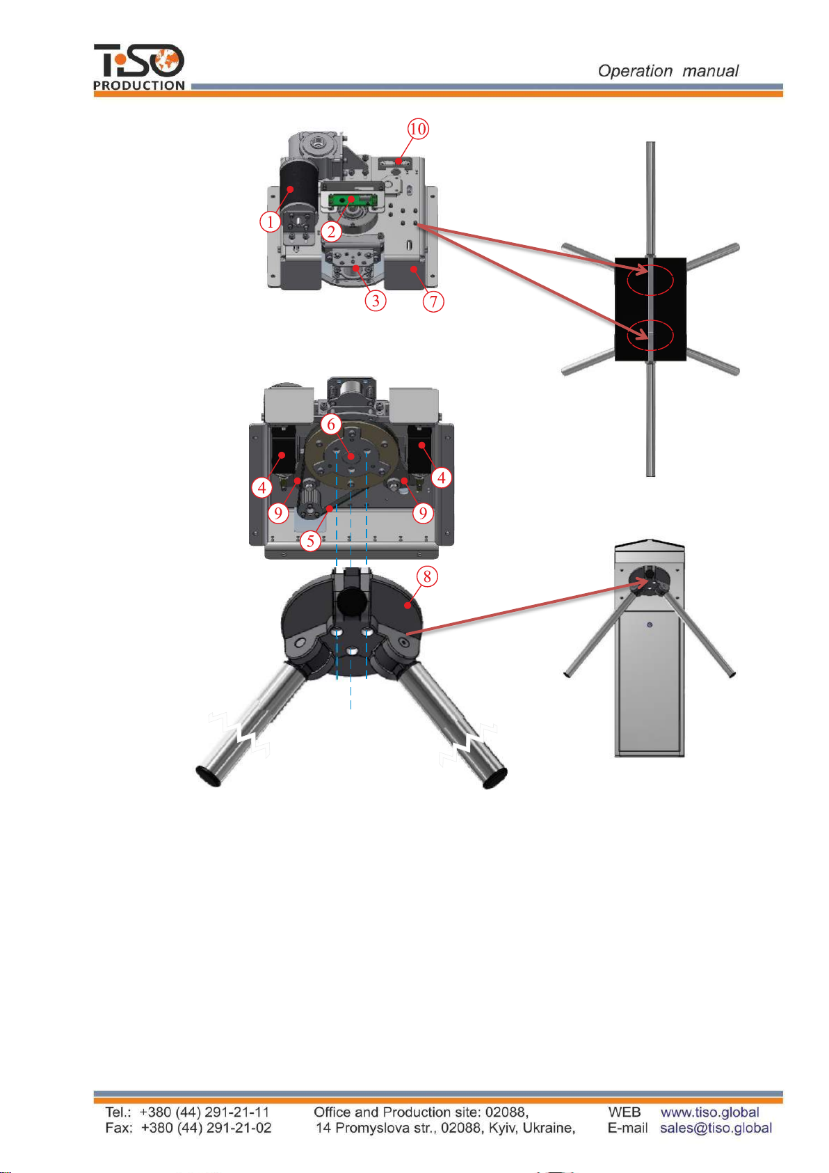
1.4.1.3 The tripod turnstile control mechanism design is shown in Figure 5.
1 –gear motor;
6 –hub shaft;;
2 –position sensor;
7 –mechanism body;
3 –antipanic device;
8 –hub with barrier rods;
4 –locking solenoid;
9 –stop catches;
5 –driving belt;
10 –mechanism connectors;
Fig. 5 –Turnstile actuating mechanism
1.4.3 Turnstile principle of operation
1.4.3.1 Turnstile operation modes:
1) single access in the direction “A” or “B”;
2) locking;
Ce manuel convient aux modèles suivants
5
Table des matières
Autres manuels Tiso Tourniquet

Tiso
Tiso JETPAN Manuel utilisateur

Tiso
Tiso T3.PKC.XC Manuel utilisateur

Tiso
Tiso TRACK-AS-YOU-GO PRO Manuel utilisateur

Tiso
Tiso Gate-GS Manuel utilisateur

Tiso
Tiso T1.1.BYO Series Manuel utilisateur

Tiso
Tiso ASTM F2656 M40 Manuel utilisateur

Tiso
Tiso ASTM F2656 M50 Manuel utilisateur

Tiso
Tiso SpeedBlade T3.KCD.XV.X Series Manuel utilisateur


