Theta Digital 30P Manuel utilisateur
POWER \ PHASE ANGLE \ POWER FACTOR TRANSDUCER
2-60-006-00-00538
Operating Manual
T heta 30P
Rev.C - 31/5/13
ON O 1 O/P2/P C O M
T h a Pet 30


CAUTION
The proper and safe operation of the device assumes
that the Operating Instructions are read and the safety
warnings given in the various sections
Mounting,Electrical Connections, Commissioning are
observed.
All operations concerning installation, electrical
connection & commissioning must be carried out by
qualified, skilled personal & national regulations for the
preventions of accidents must be observed.
If the equipment is used in used in a manner not specified
by the manufacture, the protection provided by the
equipment may be impaired.
Read & understand this manual before using the Instrument
3

POWER \ PHASE ANGLE \ POWER FACTOR TRANSDUCER
Installation
& Operating Instructions
Section
Contents
1. Introduction
2. Input and Output screens
3. Programming
3.1 Programming Via Front LCD & Two keys
3.1.1 Password Protection
3.1.1.2 Editing Existing Password
3.1.1.1 Password Verification
3.1 Parameter Setting .7 Communication
3.1.7.1 Address Setting
3.1.7.2 RS 485 Baud rate
3.1.7.3 RS 485 Parity selection
3.1.6 Current Parameter Setting Transformer
3.1 Transformer.6.2 Current Secondary Value
3.1.6.1 Current Transformer Primary Value
3.1.5 Potential Transformer Parameter Setting
3.1 Potential Transformer.5.2 secondary value
3.1.5.1 Potential Transformer primary value
POWER \ PHASE ANGLE \ POWER FACTOR TRANSDUCER
4
3.1.3 System Type Selection
3.1.4 Output Type Selection
3.1.4.1 Output 1 Type Selection
3.1.4.2 Output 2 Type Selection
3.1.2 Transducer Type Selection

3.1 Output Characteristics setting.9
3.1 .1 Output 1 Characteristics setting.9
3.1.9.1.1 End value of output 1
3.1.9.1.2 Start value of output 1
3.1.9.1.3 Elbow value of output 1
3.1 .2 Output 2 Characteristics setting.9
3.1.9.2.1 End value of output 2
3.1.9.2.2 Start value of output 2
3.1.9.2.3 Elbow value of output 2
3.1.10 Mode Selection
3.2
Programming Via Programming port available at front of
Transducers using optional PRKAB601 Adapter
3.3
Programming Via optional RS485
RS 485 Modbus ( )
4.
Phaser Diagram
5.
6. Installation
6.1 EMC Installation Requirements
6.2 Case Dimensions
6.3 Wiring
6.4 Auxiliary Supply
8.
Connection Diagrams
6.5 Fusing
6.6 Earth / Ground Connections
Specifications
7.
3.1 Input Setting.8 Characteristics
3.1.8.1 End value of Input
3.1.8.2 Start value of Input
3.1.8.3 Elbow Function Selection
3.1.8.4 Elbow value of input
5
DIP Switch Setting for Changing Output type
3.3.1
(MODBUS)
communication port.
6.7 Maintenance
1. Introduction
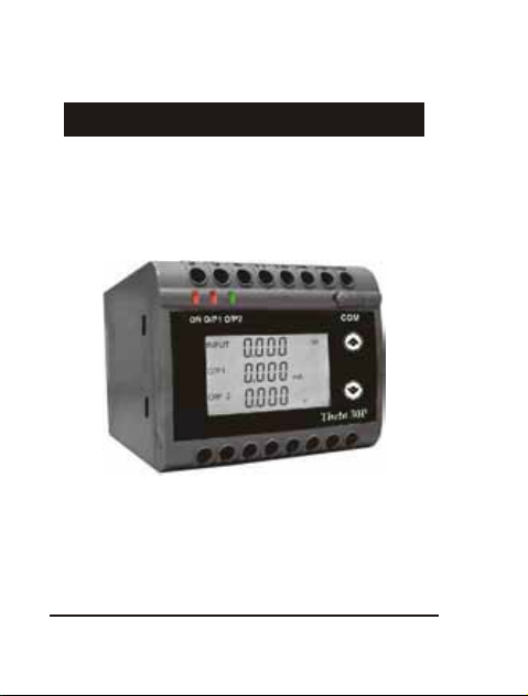
The POWER/PHASE ANGLE/ POWER FACTOR TRANSDUCER is a DIN
The is used to measure and convert Active, Apparent, Reactive Transducer
Power, Phase Angle & Power Factor of a Single phase or Three phase AC
or voltage output signal.
System with balanced or unbalanced load into an proportional DC current
Transducer an be configured c
and programmed on site for the
The front panel has two push buttons through which the user can enter
into programming mode and can configure the transducer.
PT Primary ,PT Secondary,
CT Primary, CT Secondary, Input
Characteristics (i.e start, end
and elbow value of Input) and
Output Characteristics (i.e Voltage or Current and start, end and
6
following :
elbow Value of outputs.)
INPUT
O/P1
O/P 2
VA
mA
V
.
.
1.1: LED Indication
Green LED continuous ON
Aux. Supply healthy condition
ON
LED LED OPERATING CONDITION LED OPERATING STATUS
Output1 Voltage Green LED continuous ON
O/P 1 Output1 Current Red LED continuous ON
Output2 Voltage Green LED continuous ON
O/P 2 Output2 Current Red LED continuous ON
Rail/Wall mounted 78.5 X 65.5mm Transducer.

Table 1: Measured parameters
Measured parameters Unit of Measurement
W
Active Power
Reactive Power VAr
VA
Apparent Power
Power Factor
°(DEG)
Phase Angle
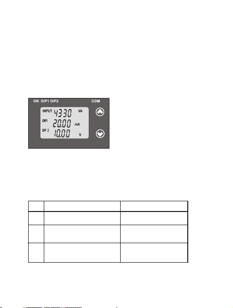
2. Input and Output screens
In normal operation the user is presented with display test screen
followed by version screen to one of the output screen.
7
Output 1 as Current or Voltage
For Reactive Power Transducer,
Output 1 as Current or Voltage
For Apparent Power Transducer :
Output 2 as Current or Voltage Output 2 as Current or Voltage
–
Input Apparent Power, Input Reactive Power,
INPUT
O/P1
O/P 2
VA
mA
V
.
.
INPUT
O/P1
O/P 2
VAr
mA
V
.
.

Output 1 as Current or Voltage
Input Active Power,
Output 2 as Current or Voltage
Output 1 as Current or Voltage
Input Power Factor,
Output 2 as Current or Voltage
Output 1 as Current or Voltage and Output 2 as Current or Voltage
For Phase Angle Transducer
3. Programming
Programming of transducer can be done in three ways :
3.1. Programming Via Front LCD & Two keys.
3.2. Programming Via Programming port available at front of
Transducers using optional PRKAB601 Adapter.
3.3. Programming Via optional RS485(MODBUS) communication port.
The following sections comprise step by step procedures for
configuring the Transducer for individual user requirements.
3.1: Programming Via Front LCD & Two keys
For Active Power Transducer, For Power Factor Transducer
Input Phase Angle
INPUT
O/P1
O/P 2
W
mA
V
.
.
-
.
.
.
INPUT
O/P1
O/P 2
PF
mA
V
-
-
-
.
.
INPUT
O/P1
O/P 2
Angle
mA
V
8

*
To access the set-up screens press and hold the “ Down” and “
Up” keys simultaneously for 5 seconds. This will take the User to
the password screen .
3.1.1: Password Protection:
Password protection can be enabled to prevent unauthorized access
to set-up screens, by default password protection is not enabled.
Password protection is enabled by selecting a four digit number other
than 0000. Setting a password of 0000 disables the password protection.
3.1.1.1: Password Verification
P ressing the “ Down” key will
Enter Password, prompt for first digit.
(*Denotes that digit will be flashing).
0 to 9 and the value will roll back again
to 0. Pressing the “ Up” key will
scroll the value of the first digit from
advance the operation to next digit and set the first digit.
9
In the special case where the Password is “0000” pressing the “ Up”
key when prompted for the First digit will advance to the “Password
Confirmation”mode.
*
After first digit gets entered, it will
prompt for second digit.
(*Denotes that digit will be flashing).
P ressing the “ Down” key will
from 0 to 9 and the value will roll
scroll the value of the second digit
Pressing the “ Up” key will advance the Operation to the next
digit and set the second digit.
back again to 0.

After, second digit gets entered, it
will prompt for third digit.
(*Denotes that digit will be flashing).
Pressing the “ Down” key will
scroll the alue of the third digit from v
0 to 9 and the value will roll back
Pressing the “ Up” key will advance the Operation to the next
digit and set the third digit.
*
*
After, third digit get entered, it will
prompt for fourth digit.
(*Denotes that digit will be flashing).
Pressing the “ Down” key will
scroll the alue of the fourth digit from v
0 to 9 and the value will roll back
again to 0.
Pressing the “ Up” key will advance the Operation to the next
10
Pressing “ Down” key will enter
to the “ Password edit ”
Confirmation of Password
advance to the Transducer Type
Pressing the “ Up” key will
mode .(section 3.1.1.2)
selection (section 3.1.2).
again to 0.
digit and set the fourth digit.
Manuels Transducteur populaires d'autres marques


Mianyang Weibo Electronic
Mianyang Weibo Electronic WB Series Manuel utilisateur

ProMinent
ProMinent Dulcometer DMT Manuel utilisateur

MKS
MKS MicroPirani 925 Series Comment utiliser

WIKA
WIKA WU-20 Manuel utilisateur

Alcatel Vacuum Technology
Alcatel Vacuum Technology BARATRON 622A Manuel utilisateur

Camille Bauer
Camille Bauer SIRAX CH-5610 Manuel utilisateur


