Teleorigin RB600 Manuel utilisateur

1

Contents
1. Overview............................................................................................................................4
2. References.........................................................................................................................5
3.Package..............................................................................................................................6
3.1 Box......................................................................................................................................... 6
4. Complete package contents..............................................................................................
5. General presentation.........................................................................................................8
5.1 Product pictures......................................................................................................................8
5.2 External connections..............................................................................................................9
5.2.1 GSM antenna connector..................................................................................................9
5.2.2 Bluetooth antenna connector.........................................................................................10
5.2.3 RS-232 Interface (EIA5 4)............................................................................................11
5.2.4 Power supply connector................................................................................................12
5.2.5 SIM card holder.............................................................................................................13
5.3 Product sticker....................................................................................................................14
6. Basic features and services.............................................................................................15
. Using the modem.............................................................................................................16
.1 Setting up the modem...........................................................................................................16
.2 Mounting the modem on the wall.........................................................................................16
.3 Checking the communication with the modem.....................................................................1
.4 Status of the modem (LEDs)................................................................................................1
.5 Disabling and enabling echo function...................................................................................18
.6 Verifying the strength of received signal...............................................................................19
. PIN code status................................................................................................................... 19
.8 Network registration.............................................................................................................. 20
.8.1 GSM network registration..............................................................................................20
.9 GPRS network registration...................................................................................................21
.10 AT commands summary.....................................................................................................22
8. Troubleshooting................................................................................................................23
8.1 No connection/communication with the modem....................................................................23
8.2 Receiving ERROR message................................................................................................23
8.3 Receiving NO CARRIER message.......................................................................................24
9. Technical characteristics..................................................................................................25
9.1 Mechanical characteristic.....................................................................................................25
9.2 Housing description (dimensioning diagram)........................................................................25
2

10. Electrical characteristic..................................................................................................26
10.1 Power supply......................................................................................................................26
10.2 RF characteristics...............................................................................................................26
10.3 External antenna................................................................................................................2
10.4 Environmental characteristic...............................................................................................2
11. Safety recommendations...............................................................................................28
11.1 General Safety....................................................................................................................28
11.2 Care and Maintenance........................................................................................................28
11.3 Responsibility...................................................................................................................... 28
12. Conformity Assessment Issues......................................................................................29
13. Safety Recommendations..............................................................................................30
14. List of Acronyms.............................................................................................................31
15. On-line support...............................................................................................................33
3

1. Overview
The RB600 Terminal is the complete modem solution for wireless m2m applications.
Based on the high quality module, it is available as quad-band version and offers high
level GSM/GPRS communication and GNSS receiver in a compact plastic housing with all
the standardized interfaces. Together with its small size and wide supply voltage range, it
is easy to integrate into all kinds of machines.
The RB600 terminal utilises TCP/UDP data transmission, SMS and SMTP
communication. It is a universal solution for all low-volume M2M and mobile data
applications including metering, traffic systems, transportation and logistics, security,
vending machines and facility management.
Device can be controlled by standard AT commands or by customer's application, thus
making it the smallest, complete SMT platform for m2m solutions.
This document contains full description of the RB600 modem and gives information
about installation and using it.
4

2. References
[1] Quectel_MC60_Series_AT_Commands_Manual_V1.0
5

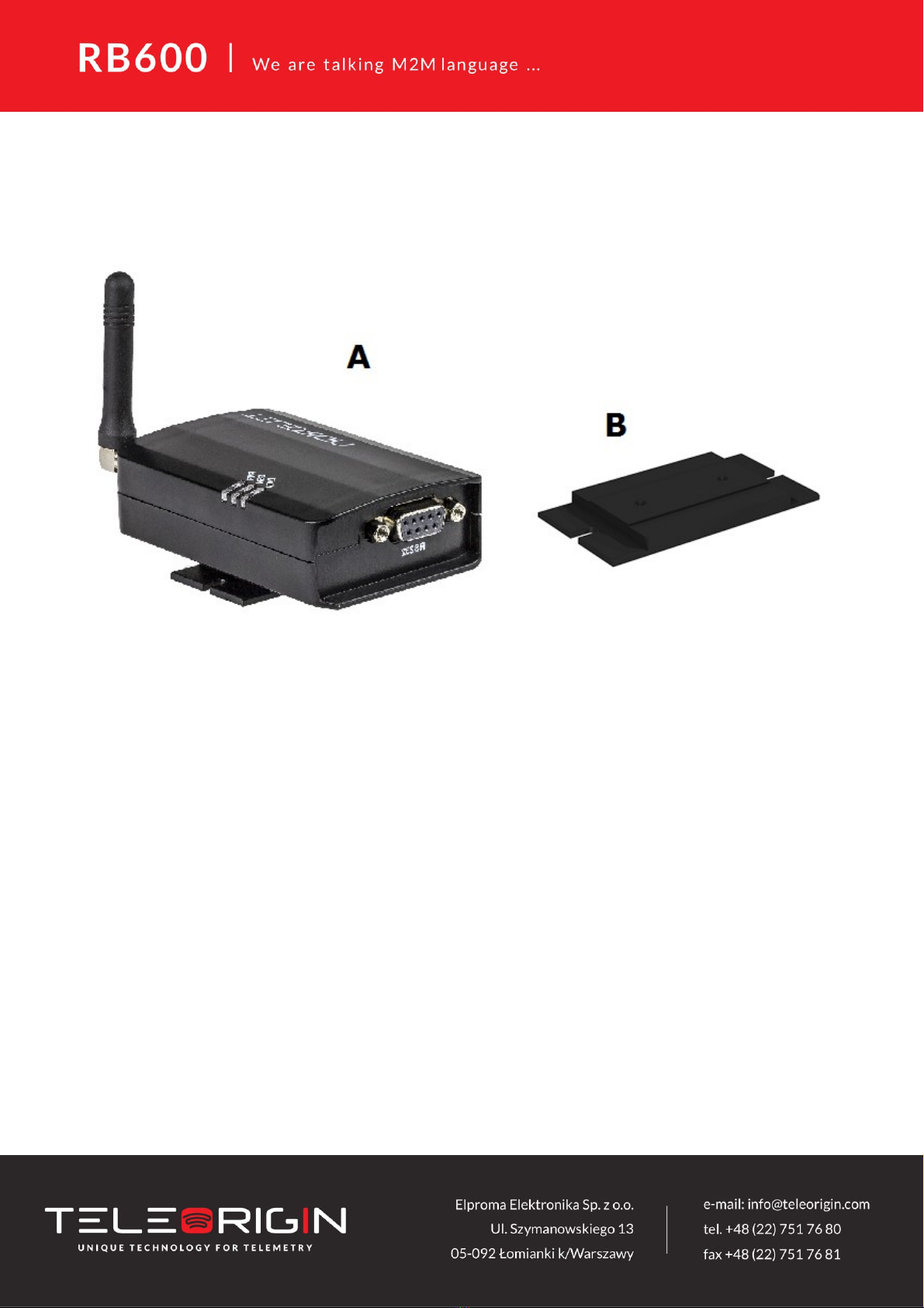
4. Complete package contents
Complete package contains:
RB600 terminal (item A)
Wall mounting bracket (item B)

. General presentation
.1 Product pictures
8
SMA
antenna
Extractable
SIM card
holder
SIM card
holder
ejector
Power
supply
EIA574 (RS- 3 )
DE9 D-sub socket
DATA
GSM
PWR
LED's

.2 External connections
.2.1 GSM antenna connector
The SMA antenna input is used to connect an external GSM antenna. To establish
a connection with GSM network, an external antenna must be used. The type of antenna
depends on GSM coverage. In good circumstances (level of received signal is high) use
antenna which is included in the package. If the range of GSM is low or zero, an outdoor
or indoor (for instance in a place where GSM range is sufficient) antenna should be used.
Note: If there is no antenna connected to the SMA connector, connection with a GSM
network is impossible.
9

.2.2 RS-232 Interface (EIA 74)
RB600 terminal is equipped with an RS-232 interface (as shown below). A DE9 DSUB
socket is connected via a voltage level translator circuit to the GSM module.
Table of RS-232 DB9 pins:
Pin No. Name Dir Description
1 DCD IN Data Carrier Detect. Raised by DCE when modem
synchronized.
2 RD IN Receive Data (a.k.a RxD, Rx). Arriving data from DCE.
3 TD OUT Transmit Data (a.k.a TxD, Tx). Sending data from DTE.
4 DTR OUT Data Terminal Ready. Raised by DTE when powered on. In
auto-answer mode raised only when RI arrives from DCE.
5 SGND - Ground
6 DSR IN Data Set Ready. Raised by DCE to indicate ready (optionally
RS485 A)
RTS OUT Request To Send. Raised by DTE when it wishes to send.
Expects CTS from DCE.
8 CTS IN Clear To Send. Raised by DCE in response to RTS from DTE.
9 RI IN Ring Indicator. Set when incoming ring detected - used for auto-
answer application. DTE raised DTR to answer (optionally
RS485 B)
DE-9 (EIA/TIA 5 4)
View of the female connector
10
Table des matières
Manuels Terminal tactile populaires d'autres marques

Wincor Nixdorf
Wincor Nixdorf iPOS plus Advanced Manuel utilisateur

Ingenico
Ingenico AXIUM EX4000 Manuel utilisateur

Heisei Electronics
Heisei Electronics Q-POS 815 Manuel utilisateur

Amano
Amano MTX-15 Manuel utilisateur

FLOWBIRD
FLOWBIRD CWT Compact Touch Manuel utilisateur

Demco
Demco SP7 Manuel utilisateur


