Page v
Telect, Inc. • USA +1.509.926.6000 • Mexico +52.33.3836.37.52
www.telect.com • © 2010 Telect, Inc., All Rights Reserved, 126254-4 A0.1
Figure 17 - LCX Patch Panel, 4RU — 72, 96, or 144 Termination ............................................12
Figure 18 - Patch Plates ............................................................................................................ 12
Figure 19 - WDM & Splitter Modules .........................................................................................13
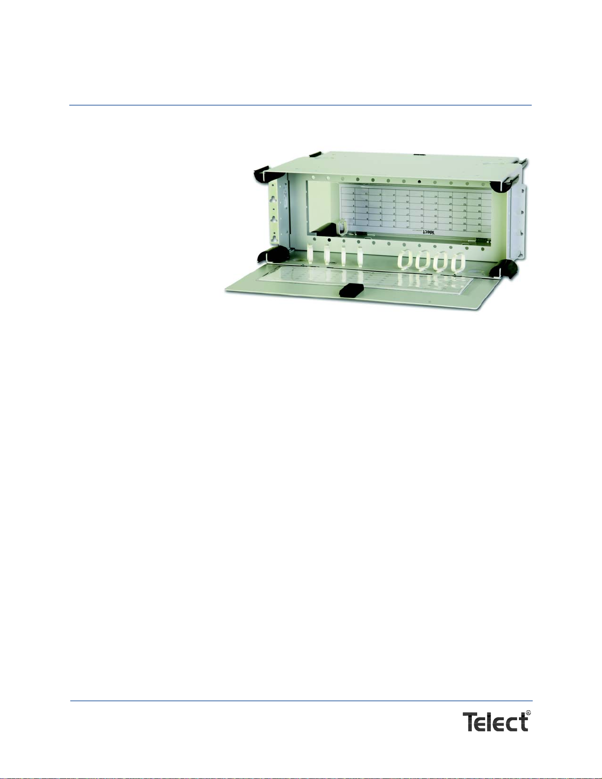
Figure 20 - 1RU LCX Chassis ....................................................................................................16
Figure 21 - 2RU LCX Chassis ....................................................................................................17
Figure 22 - 3RU LCX Chassis ....................................................................................................18
Figure 23 - 4RU LCX Chassis ...................................................................................................19
Figure 24 - Pull-Out & Swing-Out Clearances ........................................................................... 20
Figure 25 - Interconnecting/Splicing Facility Cable to Network Elements .................................. 21
Figure 26 - Interconnecting Network Elements in a LCX Fiber Patch Panel .............................21
Figure 27 - Cross-Connecting Network Elements ...................................................................... 22
Figure 28 - Cross-Connecting IFC to Network Elements ...........................................................23
Figure 29 - Interconnecting/Cross-Connecting Along with WDM/Splitter Modules .................... 25
Figure 30 - Removing Knockouts & Installing Plastic Grommets ............................................... 28
Figure 31 - Installing a Standard Split Arc .................................................................................29
Figure 32 - Installing a Standard Isolation Hook Kit ...................................................................29
Figure 33 - Installing An Optional Arc Kit ...................................................................................30
Figure 34 - Mounting LCX Panel to Rack ..................................................................................30
Figure 35 - Installing Adapter Pack & Special Function Modules .............................................. 31
Figure 36 - Inserting Cabling Rings ..........................................................................................31
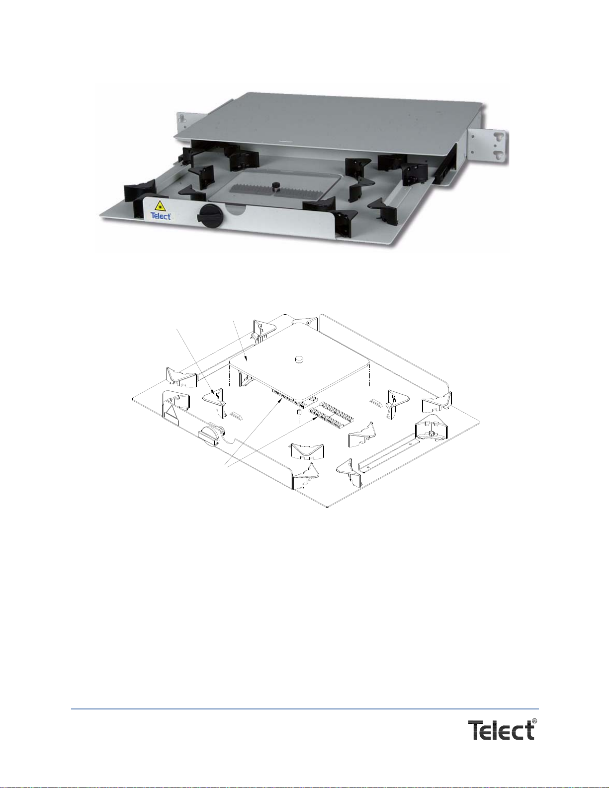
Figure 37 - Cable Restraint Layout (Top View of Chassis Bottom) ...........................................32
Figure 38 - Mounting 1RU LCX Panel to Rack ..........................................................................32
Figure 39 - Mounting 1RU LCX Combo Panels to Rack ............................................................33
Figure 40 - Installing Patch Plates & Special Function Modules in a 1RU ................................. 33
Figure 41 - IFC Breakout Length (2RU through 4RU) ...............................................................36
Figure 42 - IFC Clamp ............................................................................................................... 37
Figure 43 - Installing IFC for Splicing ......................................................................................... 37
Figure 44 - Cable Placement and Securing ...............................................................................38
Figure 45 - Splice Tray (Right Corner View) ............................................................................. 39
Figure 46 - Splice Tray (Fiber Routing) ......................................................................................40
Figure 47 - Installing Interconnects or Cross-Connects in an LCX Fiber Patch Panel .............. 41
Figure 48 - IFC Breakout Length (1RU) .....................................................................................42
Figure 49 - Installing an IFC for a LCX 1RU Panel.................................................................... 43
Figure 50 - Cable Routing .......................................................................................................... 44
Figure 51 - 1RU Splice Tray (Right Corner Tray) ......................................................................45
Figure 52 - 1RU Splice Tray (Fiber Routing) ............................................................................. 45
Figure 53 - Cleaning the Adapter ...............................................................................................48