© Telect, Inc., All Rights Reserved, 143252-1 A0
1.509.926.6000 :: telect.com
6
Dual 150A 4/4 TPA/GMT Fuse Alarm Panel
Power :: 009-8005-3404H
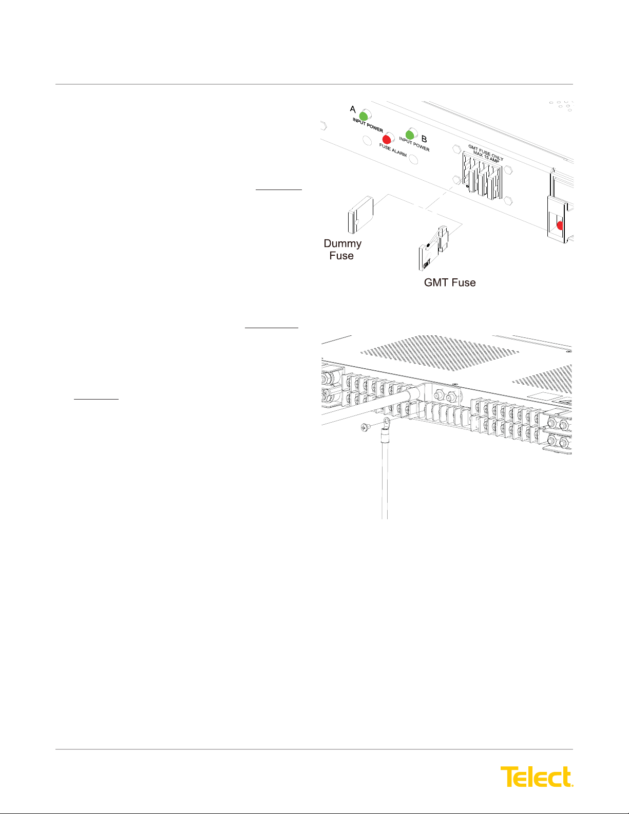
16. Make sure the TPA and GMT fuse positions are
either empty or contain dummy fuses (phoney,
inoperative all plastic slugs).
If necessary, pull out the TPA carrier about an inch
from its holder to disengage the TPA fuse,
as shown in Figure 6.
17. Enable the fuse or breaker at the PDU to turn on
Feed A to Side A of the panel and then measure
the voltage and check polarity at input connectors
of panel. Also, check that
• INPUT POWER A LED on front of panel turns on
(green). (See Figure 7 for location.)
• All other LEDs must be off.
18. With the INPUT POWER A lit (normal operation)
— but with all other LEDs off (failure operation)
— test the power-fail relay contacts at the rear
of the panel:
• Expect an open circuit (00Ω) between Terminals C
and NC.
• Expect continuity (0Ω) between Terminals Cand
NO.
19. Also, test the fuse alarm relay contacts at the FUSE
ALARM terminals on the rear of the panel.
• Expect continuity (0Ω) between Terminals Cand
NC.
• Expect an open circuit (00Ω) between Terminals C
and NO.
20. Repeat Steps 17 through 19 to power up Side B.
21. With all INPUT POWER LEDs lit (normal operation),
test power-fail relay and contacts at PWR FAIL
terminals on the rear of the panel.
• Expect continuity (0Ω) between Terminals Cand
NC.
• Expect an open circuit (00Ω) between Terminals C
and NO.
22. Make sure none of the fuse positions are engaged
or contain operable fuses.
Figure 6 - Disengaging a TPA Fuse Holder
Figure 7 - Alarm Indicators
C.GND
NO C NC NO C NC
FUSE ALARM PWR FAIL
Figure 8 - Alarm Terminals