20
5 - 6 STOP
STOP button N.C. input – Stops the automation in any position, temporarily pre-
venting the automatic closure, if programmed. (5= STOP - 6= COM )
NOTE: A safety micro-switch is connected to the STOP push-button. In case
the STOP input remains open for more than 5 seconds, the operator will per-
form a cycle at a slow speed to reset the operating parameters to the values
originally saved (see “Restoring automatic operation”). The micro-switch
should be connected in series to further STOP push-buttons where present.
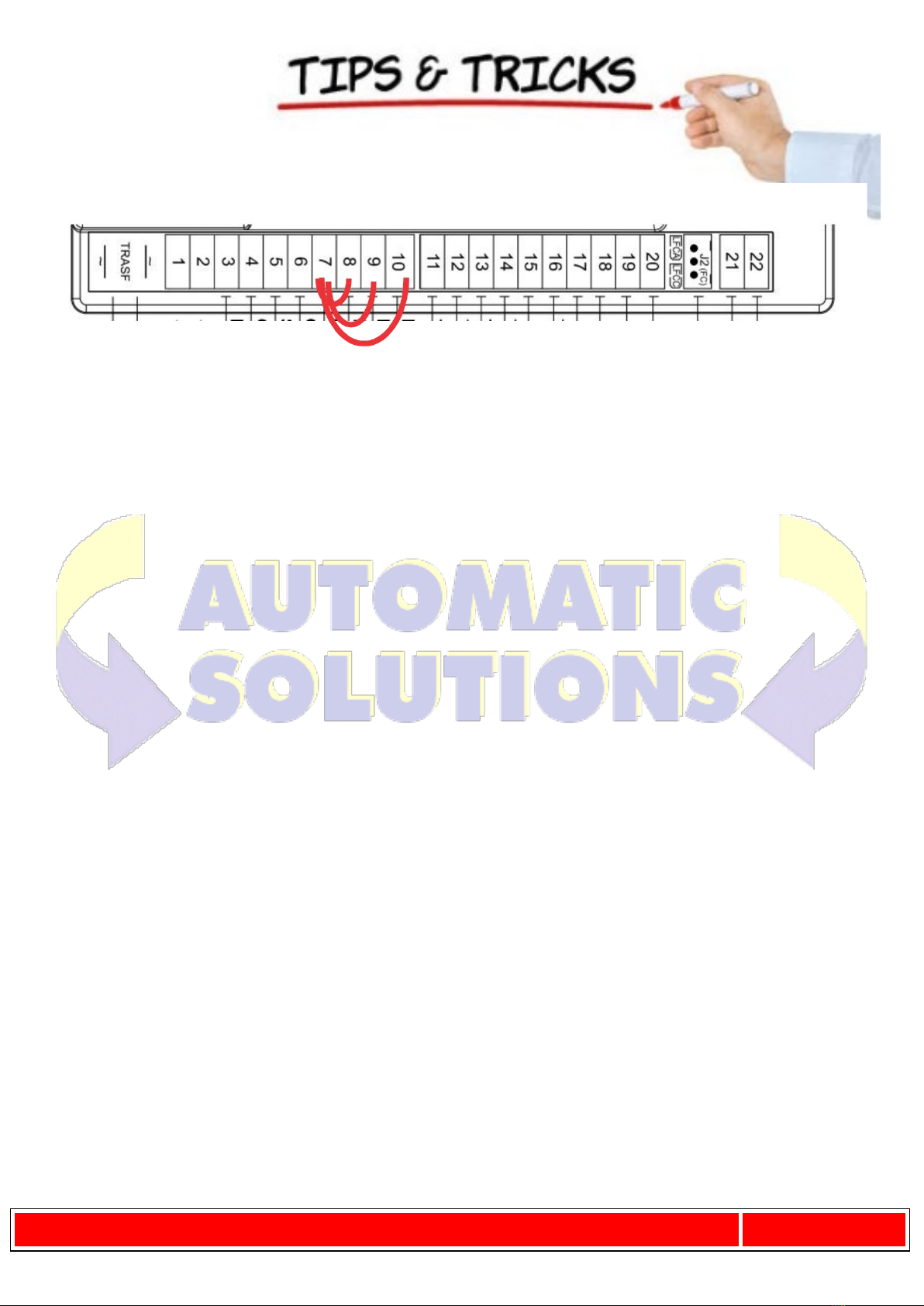
7 - 8 INTERNAL
PHOTOCELLS
PHOTOCELL OR SAFETY DEVICE input INSIDE the gate (Normally Closed con-
tact). When these devices trigger during the opening phase, they temporarily
stop the gate until the obstacle has been removed; during the closing phase
they stop the gate and then totally open it again. Bridge the connectors if
not used. (7= COM - 8= CLOSE)
7 - 9 EXTERNAL
PHOTOCELLS
PHOTOCELL OR SAFETY DEVICE input OUTSIDE the gate (Normally Closed
contact). Then these devices trigger during the closing phase, they stop the
gate and then totally open it again. Bridge the connectors if not used. (7=
COM - 9= FOT)
Note: the photocell transmitter must always be supplied by terminals
no. 12 and no. 13, since the safety system test (phototest) is carried
out on it. Without this connection, the control unit does not work. To
override the testing of the safety system, or when the photocells are
not used, set dip-switch no. 6 to OFF.
7 - 10 SENSITIVE
EDGE
SAFETY EDGE input (Resistive sensitive edge 8,2 KΩ or with n.c. contact - see
DIP SWITCH 12 ).It works during the opening phase and also during the closing
phase, resulting in the temporary stop of the automation and:
- the partial inversion of its movement for 20 cm (only in the opening phase)
- the complete opening (only in the closing phase);
thus freeing any obstacle. NOTE: if a resistive sensitive edge 8,2 KΩ is con-
nected, set dip-switch no. 12 to ON;
If a xed safety edge with NC contact is connected, set dip-switch no.
12 to OFF;
Jumper terminals if not used. (7= COMMON - 10= SENSITIVE EDGE)
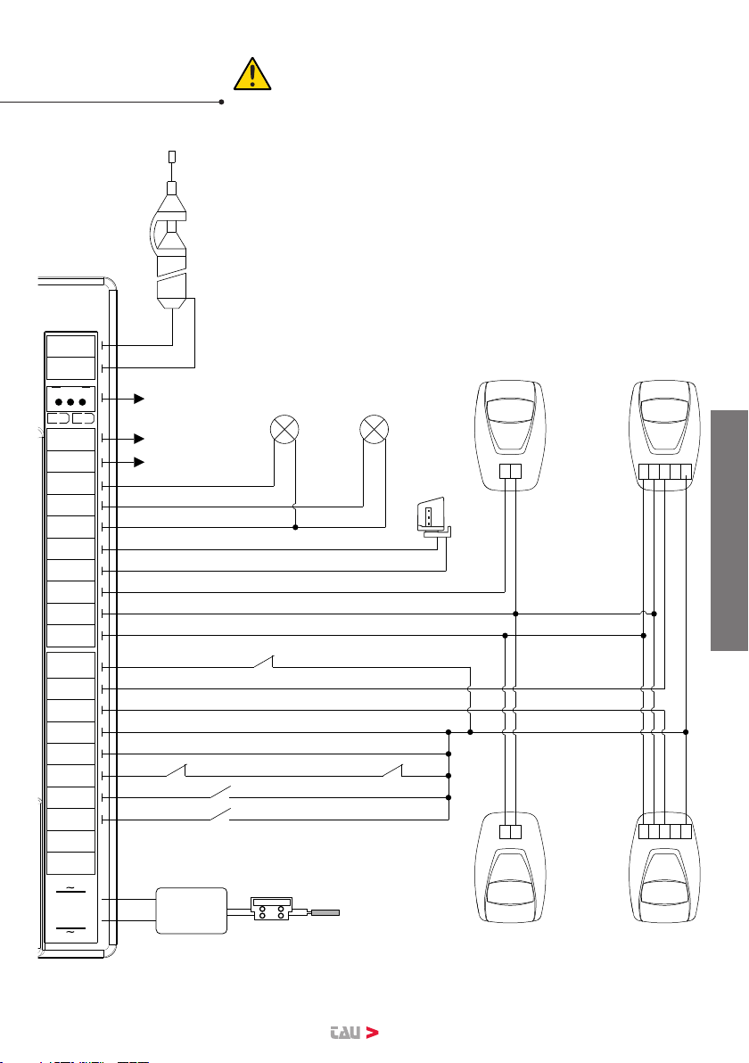
11 - 12 PHOTOCELLS output 18 V DC max. 15 W per photocells (TX/RX) and auxiliaries
(11 = NEGATIVE - 12 = POSITIVE)
12 - 13 TX PHOTOCELLS output for the 18 V DC transmitter photocell with the possibility of carrying
out the phototest (with DIP 6 ON). (12= POSITIVE - 13= NEGATIVE)
14 - 15 FLASHING
LIGHT
18V DC max. 20W output for ashing light supply, ashing signal supplied
by the control unit, rapid for closing, slow for opening.
(14= POSITIVE - 15= NEGATIVE)
16 - 17 GATE OPEN
LIGHT
Output for OPEN GATE LIGHT 18 V DC, 3 W max; while the bar opens the
light ashes slowly, when the bar is open it stays on and while closing it
ashes at twice the speed. (16= POSITIVE - 17= NEGATIVE)
16 - 18 COURTESY
LIGHT
18 V DC, 15 W Output for auxiliary courtesy light. It comes on with the
control pulse and stays ON until after the manoeuvre for a time settable
through TauApp (default = 20 sec.) (16=POSITIVE - 18= NEGATIVE)
19 - 20 2nd CH RADIO
2nd radio channel output - for control of an additional automation or for
switching on lights, etc... (N.O. clean contact)
Warning: to connect other devices to the 2nd Radio Channel (area
lighting, pumps, etc.), use an additional auxiliary relay (see note at
end of paragraph).
WARNING: the default outlet is active monostable 2 sec. To switch it
to active bistable or to modify the activation time it is necessary to
use the T-WIFI.
21 - 22 AERIAL Plug-in radio-receiver aerial input , for 433.92 MHz receivers only. (21=
GROUND - 22= SIGNAL)
23 - 24 MOTOR Motor supply output 18V DC max. 200W. (23= POSITIVE - 24= NEGATIVE)
ENGLISH