Synology NAS RS822+ Manuel

Synology NAS RS822+/RS822RP+
Hardware Installation Guide

Table of Contents
Chapter 1: Before You Start
Package Contents 3
Synology RS822+/RS822RP+ at a Glance 4
System Fans 5
System Modes and LED Indicators 6
Other LED Indicators 8
Hardware Specication 9
Spare Parts 10
Safety Instructions 11
Chapter 2: Hardware Setup
Tools and Parts for Component Installation 12
Install Drives 12
Start up Your Synology NAS 14
Install a Memory Module on Synology NAS 15
Install PCle Add-in Cards 17
Chapter 3: System Maintenance
Replace the Power Supply Unit (PSU) 18
Chapter 4: Install DSM on Synology NAS
Install DSM with Web Assistant 19
Learn More 19
Synology_HIG_RS822+/RS822RP+_20220323
2

3
Synology NAS RS822+/RS822RP+ is an enterprise server consisting of both system hardware and the software
operating system, DiskStation Manager (DSM). This manual will guide you through all conguration aspects of
your RS822+/RS822RP+, including the hardware components, setup procedures, and system maintenance.
Note: All images below are for illustrative purposes only, and may dier from the actual product.
Package Contents
Main unit x 1 AC power cord x 11
Rack mount kit x 2
Drive tray key x 2
Screws for 3.5" drives x 20 Screws for 2.5" drives x 20 Rack mount kit screws x 8
Before You Start 1
Chapter
1AC power cord: RS822+ x1; RS822RP+ x2
4Chapter 1: Before You Start
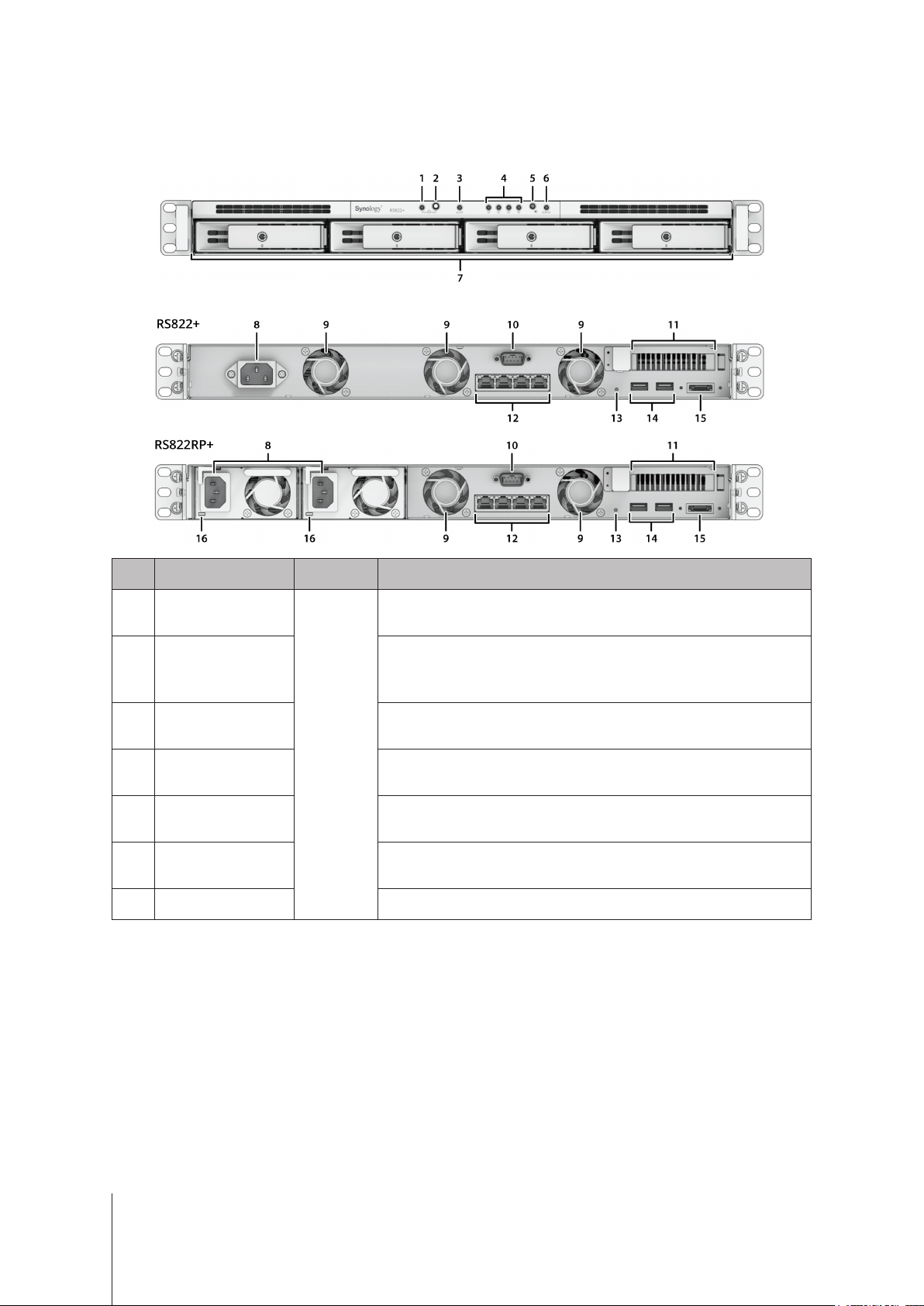
Synology RS822+/RS822RP+ at a Glance
Front
Back
No. Article Name Location Description
1 Power Indicator
Front
Displays power status of the Synology NAS. For more information,
see "System Modes and LED Indicators".
2 Power Button
1. Press to power on your Synology NAS.
2. To power o the Synology NAS, press and hold until you hear a
beep sound and the Power LED starts blinking.
3 ALERT Indicator Displays warnings regarding fan or temperature. For more
information, see "Other LED Indicators".
4 DRIVE Status
Indicator
Displays the status of each drive. For more information, see "Other
LED Indicators".
5 Beep O Button Press to deactivate the beep that sounds when a malfunction
occurs.
6 STATUS Indicator Displays the status of the system. For more information, see
"System Modes and LED Indicators".
7 Drive Tray Install drives (hard disk drives or solid state drives) here.

5Chapter 1: Before You Start
No. Article Name Location Description
8 Power Port
Back
Connect power cord here.
9 Fan Disposes of excess heat and cools the system. If the fan
malfunctions, the Synology NAS will emit a beeping sound.
10 Console Port This port is used for manufacturing only.
11 PCI Express
Expansion Slot
Supports additional PCIe network interface cards or M.2 SSD
adapter cards.
12 1GbE RJ-45 Port Connect RJ-45 network cable here
13 RESET Button
1. Mode 1: Press and hold until you hear a beep sound to restore
the IP address, DNS server, and password for the admin
account to default.
2. Mode 2: Press and hold until you hear a beep, release the
button immediately, then press and hold again until you hear
three beeps to return the Synology NAS to "Not Installed" status
so that DiskStation Manager (DSM) can be reinstalled.
For detailed information on how to reset your Synology NAS,
please refer to this article.
14 USB 3.2 Gen 1 Port Connect external drives or other USB devices to the Synology
NAS here.
15 eSATA Port Connect external SATA drive or Synology Expansion Unit1to the
Synology NAS.
16 Redundant Power
LED
Displays the status of redundant powers supplies, alerting the user
of power supply or fan failure
System Fans
If any fan failure occurs, please refer to the images below to locate the failed fan(s) indicated in DSM. The fans
are numbered as below.
To replace the failed fan(s), please contact Synology Technical Support at www.synology.com/support for
technical assistance.
1For more information about Synology Expansion Unit supported by your Synology NAS, please visit www.synology.com.

6Chapter 1: Before You Start
System Modes and LED Indicators
System Modes and Denitions
There are 7 system modes in Synology NAS. The System modes and their denitions are as below:
System mode Denition
Powering on
Synology NAS is powering on when you press the power button or restarting when
you run operations in DSM. During the boot up process, the device also performs
hardware initialization, such as hardware reset or BIOS initialization.
Shutting down Synology NAS is shutting down as a result of pressing the power button or operation
in DSM.
DSM not ready
DSM is not ready for use. This could either be:
• Synology NAS is powered on, but DSM is not properly installed.
• Synology NAS is currently powering on and initializing services necessary for
DSM to fully function.
• The attached UPS device has insucient power; DSM stops all services to
prevent data loss (enters safe mode).
DSM is ready for use DSM is fully functioning and users can sign in.
Hibernation Synology NAS has been idle for a while and is now in Hibernation mode.
Application
Certain packages/services (e.g., USB Copy and Find me service) while in operation
will control the actions of the LED. After the operation is complete, the LED indicator
will return to its normal state.
Powered o Synology NAS is powered o.
Identify System Modes
You can identify the system mode through the POWER and STATUS LED indicators. Please refer to below table
for more details.
System mode
LED Indicator
POWER STATUS
Green Green Orange
Powering on Blinking O O
Shutting down Blinking Static O
DSM not ready Static Blinking O
DSM is ready for use Static Static O
Hibernation Static O O
Application Static Switching
Powered o O O O

7Chapter 1: Before You Start
Transitions between System Modes
To better understand the transition between system modes, please refer to below examples:
• Powered on with no DSM installed:
Powered o > Powering on > DSM not ready
• Powered on with DSM installed:
Powered o > Powering on > DSM not ready > DSM is ready for use
• Enter hibernation then wake up from hibernation:
DSM is ready for use > Hibernation > DSM is ready for use
• Shutdown Synology NAS:
DSM is ready for use > Shutting down > Powered o
• Power failure with UPS attached:
DSM is ready for use > DSM not ready (due to power failure, DSM enters safe mode) > Shutting down >
Powered o > Powering on (power has recovered, DSM will reboot) > DSM not ready > DSM is ready for use

8Chapter 1: Before You Start
Other LED Indicators
LED Indicator Color Status Description
DRIVE status
Green
Static Drive ready and idle
Blinking Accessing drive
Orange1Static
Locating drive
Drive deactivated by user
Port disabled2
Drive health status is Critical or Failing
Removing this drive will cause system
damage; this is the only drive with
DSM installed
O No internal Drive
ALERT
Orange Blinking System error3
O System normal
Rear 1GbE LAN
(on right side of jack)
Green Static 1 Gbps connected
Orange Blinking 100 Mbps connected
O 10 Mbps connected/No network
Rear 1GbE LAN
(on left side of jack)
Green
Static Network connected
Blinking Network active
O No network
Redundant Power
Green Static Power supply unit normal
O Power supply unit o
Note:
1 When the drive LED indicator is orange, we recommend you sign in to DSM and go to Storage Manager >
HDD/SSD for more information.
2 Please try to restart your Synology NAS or re-insert the drives, then run the HDD/SSD manufacturer's
diagnostic tool to check the health status of the drives. If you can sign in to DSM, please run the built-in
S.M.A.R.T. test to scan the drives. If the problem remains unresolved, please contact Synology Technical
Support for help.
3 If the ALERT LED continuously blinks orange, this indicates there are system errors such as fan failure,
system overheating, or volume degrade. Please sign in to DSM for detailed information.

9Chapter 1: Before You Start
Hardware Specication
Item RS822+/RS822RP+
CPU AMD Ryzen V1500B
RAM DDR4 2 GB
Compatible Drive Type 3.5"/2.5" SATA x 4
External Port
• USB 3.2 Gen 1 x 2
• eSATA x 1
LAN Port 1GbE (RJ-45) x 4
Size (H x W x D) (mm)
• RS822+: 44 x 430.5 x 457.6 / 44 x 480 x 492.6 (with server ears)
• RS822RP+: 44 x 430.5 x 483.6 / 44 x 480 x 518.6 (with server ears)
Weight (kg)
• RS822+: 6.4
• RS822RP+: 8.0
Agency Certication • FCC Class A • CE Class A • UKCA • BSMI Class A
• EAC • VCCI • CCC • RCM • KC • UL
HDD Hibernation Yes
Scheduled Power On/O Yes
Wake on LAN Yes
Environment Requirement
• Line voltage: 100V to 240V AC
• Frequency: 50 / 60Hz
• Operating Temperature: 32 to 95˚F (0 to 35˚C)
• Storage Temperature: -5 to 140˚F (-20 to 60˚C)
• Relative Humidity: 5% to 95% RH
Note: Model specications are subject to change without notice. Please refer to www.synology.com for the latest information.

10 Chapter 1: Before You Start
Spare Parts
Visit www.synology.com/products/spare_parts if you need to replace system fans, disk trays, or power supply
units.
Model Name Picture Description
Disk Tray (Type R8) 3.5"/2.5" Drive Tray With Lock
FAN 40*20_3 System Fan 40*40*20 mm
PSU 150W-RP Module_2
PSU 150W_2 PSU 150W Open Frame
Redundant PSU Module 150W
Ce manuel convient aux modèles suivants
1
Table des matières
Autres manuels Synology Matériel informatique

Synology
Synology RX1213sas Manuel utilisateur

Synology
Synology M2D18 Manuel

Synology
Synology DS1813+ Manuel

Synology
Synology NAS DS3622xs+ Manuel

Synology
Synology DiskStation DS215+ Manuel utilisateur

Synology
Synology DiskStation DS2415+ Manuel utilisateur

Synology
Synology DX1222 Manuel

Synology
Synology RXD1219sas Manuel
Manuels Matériel informatique populaires d'autres marques

EMC2
EMC2 VNX Series Manuel du propriétaire

Panasonic
Panasonic DV0PM20105 Manuel utilisateur

Mitsubishi Electric
Mitsubishi Electric Q81BD-J61BT11 Manuel utilisateur

Gigabyte
Gigabyte B660M DS3H AX DDR4 Manuel utilisateur

Raidon
Raidon iT2300 Manuel utilisateur

National Instruments
National Instruments PXI-8186 Manuel utilisateur


