
Surface Concept Delayline DLD 8080 Manuel utilisateur

DLD8080 R4.30 & R4.31 Manual
Delayline Detector
DLD8080
(Release 4.30 & 4.31)
Manual

2DLD8080 R4.30 & R4.31 Manual | Surface Concept GmbH
Surface Concept GmbH
Am Sägewerk 23a
55124 Mainz
Germany
phone: +49 6131 62716 0
fax: +49 6131 62716 29
email: info@surface-concept.de
web: www.surface-concept.de
All rights reserved. No part of this manual may
be reproduced without the prior permission
of Surface Concept GmbH.
Delayline Detector DLD8080
Release: R4.30 & R4.31
Manual Version 2.2
Printed on 2019-08-16

3
DLD8080 R4.30 & R4.31 Manual
1 Table of Contents
1 Table of Contents ................................................................................................................................................3
2 Introduction..........................................................................................................................................................6
2.1 General Information....................................................................................................................................6
2.2 Safety Instructions .......................................................................................................................................6
2.3 General Overview of the System............................................................................................................ 7
3 Installation............................................................................................................................................................. 8
3.1 Initial Inspection............................................................................................................................................... 8
3.2 Installation .......................................................................................................................................................... 8
3.2.1 Mounting of the Delayline Detector..........................................................................................8
3.2.2 Detector Orientation.......................................................................................................................9
3.2.3 Cabling and High Voltage..............................................................................................................9
3.2.4 Software Interface and Installation......................................................................................... 11
4 Operation of the DLD......................................................................................................................................12
4.1 “Start Up“ Procedure for First Time Operation.................................................................................12
4.1.1 “Start Up“ Procedure..................................................................................................................... 12
4.1.2 Dark Count Rate Measurement................................................................................................ 14
4.1.3 Standard DLD Operation ............................................................................................................ 14
4.2 Standard Operation Procedure.............................................................................................................15
4.2.1 Operation with MCP Front Side terminated to GROUND ............................................... 15
4.2.2 Operation of the Detector with the MCP Front Side connected to a Reference Voltage16
4.3 Bake Out Procedure.................................................................................................................................. 18
5 DLD - Principle of Operation.........................................................................................................................19
5.1 Basics of Delayline Detection................................................................................................................ 19
5.2 Basic Operational Modes of the Delayline Detector .................................................................... 20
5.2.1 2D(x, y) Area Detection................................................................................................................ 20
5.2.2 3D(x, y, t) Time Resolved Imaging............................................................................................ 20
5.3 Data Acquisition ........................................................................................................................................ 21
5.4 Working with the DLD - Important Details ...................................................................................... 21
5.5 MCP Outgassing during Operation .................................................................................................... 23
DLD8080 R4.30 & R4.31 Manual | Surface Concept GmbH

4
6 Delayline Detector Layout.............................................................................................................................24
6.1 Delayline Detector - Vacuum Wiring .................................................................................................. 24
6.2 Delayline Detector - Connection Ports.............................................................................................. 25
7 Pulse Processing Electronics.........................................................................................................................26
7.1 Pulse Processing Electronics ACU 3.4.2............................................................................................. 26
7.1.1 Positions of the Discriminator Threshold Regulators ....................................................... 27
8 Micro Channel Plate (MCP)............................................................................................................................28
8.1 Specications.............................................................................................................................................. 28
8.2 Storage.......................................................................................................................................................... 28
8.3 Handling....................................................................................................................................................... 28
8.4 Operation..................................................................................................................................................... 29
8.5 MCP Lifetime and Operation Voltage ................................................................................................ 29
8.6 MCP Degase Procedure........................................................................................................................... 32
8.7 Replacement............................................................................................................................................... 32
9 Troubleshooting................................................................................................................................................33
10 Technical Data .................................................................................................................................................34
11 List of Figure.....................................................................................................................................................35
DLD8080 R4.30 & R4.31 Manual | Surface Concept GmbH

5
DLD8080 R4.30 & R4.31 Manual
DLD8080 R4.30 & R4.31 Manual | Surface Concept GmbH
6
2 Introduction
2.1 General Information
This manual is intended to assist users in the installation, operation and maintenance of Release Version
4.30 & 4.31 of the Delayline Detectors DLD8080. It is divided into 11 chapters. The chapter “Introduction”
contains a brief description of the DLD. The chapter “Installation” refers to installation and cabling, while
the chapter “Principle of Operation” explains the theory of operation of the DLD. 3 chapters describe
the technical details of the detector readout package and chapter “Operation of the DLD” describes the
operation of the DLD. The nal chapters contain among others technical details about the microchannel
plates and the Delayline Detector in general.
2.2 Safety Instructions
Pleasereadthismanualcarefullybeforeperforminganyelectrical or electronicoperations
and strictly follow the safety rules given within this manual.
The following symbols appear throughout the manual:
Note
The“note symbol”marks text passages, which contain important information/hints about
the operation of the detector. Follow these information to ensure a proper functioning
of the detector.
The “caution symbol” marks warnings, which are given to prevent an accidentally
damaging of the detector or the readout system. Do NOT ignore these warnings and
follow them strictly. Otherwise no guarantee is given for arose damages.
The “high voltage symbol” marks warnings, given in conjunction with the description of
the operation/use of high voltage supplies and/ or high voltage conducting parts.
Hazardous voltages are present, which can cause serious or fatal injuries. Therefore
only persons with the appropriate training are allowed to carry out the installation,
adjustment and repair work.
DLD8080 R4.30 & R4.31 Manual | Surface Concept GmbH

7
DLD8080 R4.30 & R4.31 Manual
2.3 General Overview of the System
The Surface Concept Delayline Detectors are particularly developed for the needs of 1D(x), 2D(x,t), 2D(x,y)
or 3D(x,y,t) area and time detection of electrons, ions, x-ray and UV-light.
The DLD8080 R4.30 & R4.31 are mounted on a CF160 vacuum ange with feedthroughs for high voltage
supply and signal transfer. They consist of a microchannel plate stack and two layers (x, y) of meander
structured delaylines. The image is sampled by the DLD readout electronics.
The 3D (x, y, t) detection bases on the measurement of time dierences and time sums of signals, with a
high temporal resolution in one device. The count rate can reach several MHz in the commonly used 4-fold
coincidence measurement.
Typical applications are:
• imaging of parallel incident particle beams, particularly electrons
• spatially resolved time of ight spectroscopy in 2D/time resolved mode
• time referenced imaging of electrons excited by repetitive driven sources
and in energy analyzers:
• Fermi surface mapping, band mapping, photoelectron diraction measurements, and similar angular
dispersion experiments in 2D mode
• XPS, UPS, ESCA and AES in virtual channel mode
• Stroboscopic experiments in 2D/time resolved mode
DLD8080 R4.30 & R4.31 Manual | Surface Concept GmbH

8
3 Installation
3.1 Initial Inspection
3.2 Installation
3.2.1 Mounting the Delayline Detector
Visual inspection of the system is required to ensure that no damage has occurred during shipping.
Should there be any signs of damage, please contact your provider immediately. Please check the delivery
according to the packing list (see Table 1) for completeness.
• Delayline Detector Unit (delivered in a vacuum container)
• Pulse Processing Unit ACU
• 1 x SHV Termination Plug
• 1 x DLD Readout Cable (HDMI) with Strain Relief
• CD with Documentation and Software
Table 1: Packing list for the DLD8080 R4.30 & R4.31 Detector.
The detector is transported under vacuum. Proceed as follows, to install the detector into your vacuum
chamber:
• Vent the transport container carefully and slowly (use N2 for venting if possible).
• Remove the transport container carefully.
• Before installing the detector to your chamber, check the front side of the MCP stack for particles.
The microchannel plates in front of the detector should be protected from exposure
to particle contamination. Particles that stick to the plate can be removed by carefully
using a single-hair brush carefully and/or with dry nitrogen. Reading the instructions
“microchannel plates” in Chapter 8 is strongly recommended.
• Install the detector into your vacuum chamber.
DLD8080 R4.30 & R4.31 Manual | Surface Concept GmbH

9
DLD8080 R4.30 & R4.31 Manual
• Keep the transport container in case that the detector must be sent back for repair. It can also be
used for storing the detector temporarily (not longer than one month) when not installed in a vacuum
chamber.
Note
The detector should be kept under vacuum all the time.
The best long term storage environment is an oil free vacuum in the 10E-2mbar range or
better.
The transport container is not designed for a long term storage of the detector. A storage
time of one month should not be exceeded.
The transport housing should be evacuated regularly with a period of at least one month,
in case that the transport housing must be used for a longer storage time.
3.2.2 Detector Orientation
The black dot in Figure 1 marks the 0/0 position of the DLD image which corresponds to the upper left
corner of the image in the GUI software.
Figure 1: 0/0 position of the DLD image (black dot).
Image 0/0 position
3.2.3 Cabling and High Voltage
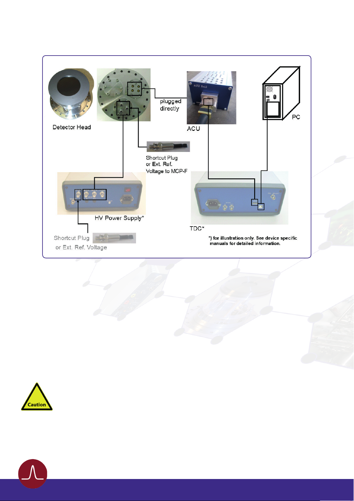
• The general connection scheme of the Delayline Detector including its readout package is shown in
Figure 2.
DLD8080 R4.30 & R4.31 Manual | Surface Concept GmbH
10
Figure 2: Connection scheme of the Delayline Detector and readout package.
• The pulse processing unit ACU can be connected directly to the DLD 4-fold SMB feedthrough. The
metal pin gives the orientation. Fasten the ACU with the two clips on the housing.
• Use the DLD readout cable to connect the “Lines Out” socket on the front of the ACU with the “TDC
Input” socket at the rear panel of the TDC (see the TDC manual for the specic connection scheme of
the TDC).
• The CF160 base ange holds 1 CF40 ange with 3 SHV feedthroughs for the high voltage supply of the
detector named “MCP-F” , “MCP-B” and “U_DLD”. The naming can be found directly engraved on the
CF40 ange.“MCP-F”is the contact to the front side of the MCP stack,“MCP-B”is the contact to the back
side of the MCP stack and “U_DLD” is connected to the detector anode.
Be sure that all voltages are settled to zero before connecting the high voltage cables to
the detector, otherwise serious damage to the detector can occur due to high voltage
sparks.
• Use the SHV cables to connect the corresponding outputs of the high voltage power supply (“MCP-F”,
“MCP-B”, and “U_DLD”) to the corresponding feedthroughs of the detector.
DLD8080 R4.30 & R4.31 Manual | Surface Concept GmbH
Autres manuels pour Delayline DLD 8080
1
Table des matières
Autres manuels Surface Concept Capteur de sécurité

Surface Concept
Surface Concept HVPS Manuel utilisateur

Surface Concept
Surface Concept DLD4040 Manuel utilisateur

Surface Concept
Surface Concept CEM 4230 Manuel utilisateur

Surface Concept
Surface Concept Delayline DLD 8080 Manuel utilisateur

Surface Concept
Surface Concept MCPD25 Manuel utilisateur

Surface Concept
Surface Concept DLD6060-8S Manuel utilisateur

Surface Concept
Surface Concept MCPD40 Manuel utilisateur

Surface Concept
Surface Concept MCPD18 Manuel utilisateur


