STMicroelectronics SensorTile STEVAL-GPT001V1 Manuel utilisateur

Introduction
The STEVAL-GPT001V1 is an add-on development kit for the STEVAL-STLCS01V1 SensorTile module.
The kit and the module create a whole system which represents a multi-sensor IoT node with increased energy autonomy
thanks to the power harvested from thin-film solar modules (under indoor or outdoor lighting conditions) and conditioned to
recharge the battery through the SPV1050TTR energy harvester and battery charger.
The STEVAL-GPT001V1 kit consists of a watch-shaped silicon strap embedding three PV panels, a cradle board (which is an
evolution of the STLCR01V1 SensorTile Cradle board) whose core product is the SPV1050TTR and the power management
section to recharge a 100 mAh Li-Po battery.
The SPV1050TTR optimizes the energy harvested from the PV panels, thanks to the embedded MPPT algorithm, and
recharges the battery while guaranteeing over-voltage and under-voltage protection; the harvested energy allows a longer
system autonomy and makes available a 3.3 V LDO output to supply the STEVAL-STLCS01V1 SensorTile module.
The customized STSW-GPT001V1 software offers a complete framework to build a typical multi-sensor node application and to
monitor battery charge, system autonomy, recharge time and the energy stored.
The firmware can be uploaded onto the STEVAL-STLCS01V1 SensorTile module via the STEVAL-GPT001V1 cradle board
SWD connector.
Figure 1. STEVAL-GPT001V1 development kit
Getting started with the STEVAL-GPT001V1 SensorTile add-on development kit
powered by thin-film solar modules
UM2260
User manual
UM2260 - Rev 2 - November 2018
For further information contact your local STMicroelectronics sales office.
www.st.com

1Getting started
1.1 Hardware description
1.1.1 Kit overview
The STEVAL-GPT001V1 kit is an add-on to the SensorTile cradle board with on-board charger for Li-Ion and Li-
Po batteries, a fuel gauge and a humidity and temperature sensor, housed in a watch-shaped silicon strap with
embedded PV solar panels.
The user can plug the STEVAL-STLCS01V1 SensorTile module to the STEVAL-GPT001V1 via a dedicated
connector (CN2).
The kit has been designed for evaluation purpose and to support the development and prototyping phase of new
projects.
A complete hardware and software file package is available at www.st.com containing:
• Hardware files (schematics, Gerber, BoM)
• Software files:
– Basic firmware (.hex), running on STEVAL-STLCS01V1 SensorTile module
– Complete software app. (.apk) to monitor and run the whole system features via smartphone and tablet
The kit features:
• Sensor Tile Cradle with SPV1050TTR energy harvester and battery charger, humidity and temperature
sensor, gas gauge, lithium battery charger, micro-USB port, ON/OFF switch and breakaway SWD connector
• 3.7 V / 100 mAh Li-Po battery
• SWD programming cable
• Silicon strap embedding the thin-film flexible solar modules and housing the SensorTile Cradle and the
battery
• Software libraries and tools:
– STSW-GPT001V1: dedicated SensorTile firmware package supporting different algorithms tailored to
the on-board sensors and computation of system autonomy and charge stored in the battery
–FP-SNS-ALLMEMS1: STM32 ODE function pack
–FP-SNS-MOTENV1: STM32Cube function pack
–STBLESensor: iOS and Android demo apps
–BlueST-SDK: iOS and Android software development kit
– Compatible with STM32 ecosystem through STM32Cube support
• STEVAL-STLCS01V1 SensorTile module (not included in the kit)
• Firmware debug/upload through the SWD connector and cable
• RoHS and WEEE compliant
1.1.1.1 Watch-shaped silicon strap
The watch-shaped silicon strap has been designed to embed high efficiency flexible PV panels and to host both
the STEVAL-GPT001V1 cradle board and the 100mAh battery provided in the STEVAL-GPT001V1 development
kit.
The PV panels are connected to the input stage of the STEVAL-GPT001V1 cradle board.
As shown in Figure 1. STEVAL-GPT001V1 development kit:
• A PV panel is embedded in the front quadrant and can reach up to about 4 mW;
• Two PV panels are embedded in the lateral straps and each of them can provide up to about 2 mW each at
1 Sun.
The four PV panels embedded in the strap are connected in parallel, so that, in total, they can supply up to 8 mW
at 1 Sun.
Three dedicated slots are available on the back and right side of the quadrant for direct access to the SWD, to the
micro-USB connector and to the ON/OFF switch (SW1).
UM2260
Getting started
UM2260 - Rev 2 page 2/25
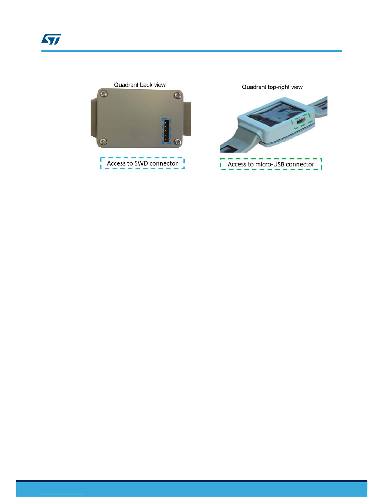
Figure 2. STEVAL-GPT001V1 kit: smart watch direct access points
The back cover can be removed to access the battery and the STEVAL-GPT001V1 cradle board.
1.1.1.2 STEVAL-GPT001V1 cradle board
The STEVAL-GPT001V1 cradle board hosts and supplies the STEVAL-STLCS01V1 SensorTile module; it
increases the autonomy of the SensorTile module when the 5 V USB supply source is not available, thanks to the
harvested energy provided by the PV panels.
The cradle board features:
• A pluggable or solderable interface (CN2) for the STEVAL-STLCS01V1 SensorTile module
•SPV1050TTR – high efficiency harvester, battery charger and power manager
• SW1 - ON/OFF switch to enable/disable the LDO supplying the SensorTile module
•STBC08PMR – 800 mA standalone linear Li-Ion battery charger
•HTS221 – capacitive digital sensor for relative humidity and temperature
•STC3115 – fuel gauge IC
•USBLC6-2P6 – very low capacitance ESD protection
• USB type A to micro-B USB connector for power supply and communication
• SWD connector for programming and debugging
1.1.1.3 Battery
The battery included in the kit is a one cell (3.7 V) lithium polymer battery able to supply up to 100 mAh (refer to
Section 1.4.5 STEVAL-GPT001V1 programming interface for instructions on how to connect the battery to the
STEVAL-GPT001V1 cradle board).
1.1.1.4 SWD cable
The five-way SWD cable easily allows the STEVAL-GPT001V1 cradle board to be connected to a programmer/
debugger system such as ST-LINK V2.1 (refer to Section 1.4.5 STEVAL-GPT001V1 programming interface for
further details on the programming interface).
1.2 Software description
The STSW-GPT001V1 software available with the STEVAL-GPT001V1 development kit is based on the STSW-
STLKT01 SensorTile kit software, with the addition of the following functions:
•Running mode, which calculates the system autonomy on the basis of the battery current sensed by
STC3115 through resistor R9. This computation is based on the STEVAL-STLCS01V1 module average
current consumption when the PV modules constitute the available energy source. The software returns the
battery charge level, the average current consumption and the estimated overall system autonomy.
•Sleep mode: the interrupt to wake up the microcontroller is provided by the accelerometer output being
inactive for a time period longer than 1 minute by default. It can be changed and set up according to the
specific firmware needs. In this condition, the RTC of the microcontroller remains active to count the time
elapsed during the low power consumption mode. Battery charge measurement just before and after the
sleep mode allows calculating the amount of charge stored during this time frame.
UM2260
Software description
UM2260 - Rev 2 page 3/25

1.3 STBLESensor app description
1.3.1 SensorTile module activation and transmission
When active (see Section 1.4.1 Startup), the SensorTile module can transmit the environmental data to
STBLESensor app for smartphones and tablets.
To start transmitting data, the SensorTile module has to be virtually connected to the app by the scan procedure
described below.
Step 1. Launch the STBLESensor app
Step 2. Click on the Start Scanning icon
Figure 3. STBLESensor app - Start Scanning tab
Step 3. After a few seconds the app will show the SensorTile module device list identified by the scanning
procedure.
UM2260
STBLESensor app description
UM2260 - Rev 2 page 4/25

Figure 4. STBLESensor app - Device List tab
Step 4. After having selected one among the available devices, the app will automatically move to the
Environmental tab showing the ambient temperature [°C], pressure [mBar] and humidity [%] values:
UM2260
STBLESensor app description
UM2260 - Rev 2 page 5/25

Figure 5. STBLESensor app - Environmental tab
Step 5. Scroll the display to left/right to move over the different tabs available in the app (plots of environmental
sensors, accelerometer, Rssi and battery information).
1.3.2 Rssi and Battery information tab
The Rssi and Battery information tab shows the transmission signal Rssi level and a fully detailed information list
related to the battery when the system is powered by solar modules:
•Charging level [%]
• Status (Discharging/Charging)
• Voltage [V]
• Current [mA] (net current = charging current minus load current)
• Estimated system autonomy [minutes], according to the charge level and to the current drained by the load
The harvested current allows increasing the system autonomy significantly.
The figure below shows the Rssi and battery information tab in 3 different cases:
• without any external recharge source connected to the cradle board (neither USB nor PV panels)
• with PV panels
• with a USB source connected
UM2260
STBLESensor app description
UM2260 - Rev 2 page 6/25

Figure 6. STBLESensor app - Rssi and Battery information tab
The figures below show the increase of system autonomy in minutes thanks to the lighting energy from 6500 K
fluorescent lamp (250 to 5 k Lux) and solar (from 0.06 and 1 W/m2) light conditions.
Figure 7. System autonomy vs. irradiance (indoor)
UM2260
STBLESensor app description
UM2260 - Rev 2 page 7/25

Figure 8. System autonomy vs. irradiance (outdoor)
The STSW-GPT001V1 firmware is designed to automatically enter a low consumption mode (sleep mode) in case
the app is closed (BLE network processor inactive) and after one minute of inactivity of the SensorTile module
accelerometer.
The system automatically restarts working normally when the accelerometer detects a movement.
In the Rssi and Battery information tab, it is possible to monitor system sleep time duration and the amount of
charge accumulated at the same time (Delta Charge), as shown in the following picture.
UM2260
STBLESensor app description
UM2260 - Rev 2 page 8/25

Figure 9. STBLESensor app - Rssi and Battery information tab after sleep mode
1.4 System setup
1.4.1 Startup
To start the system up, the SensorTile module and the battery must be plugged into the cradle board; the battery
has to be supplied by the PV panels or by a 5 V source otherwise it remains electrically isolated.
The STEVAL-GPT001V1 cradle board power management architecture electrically connects the battery when the
voltage on the SPV1050TTR STORE pin triggers the 4.1 V EOC threshold (set by the resistor partitioning R14,
R15 and R16) and the Q1 pass transistor is consequently activated (see Section 1.4.3.2 Protection).
The PV panels supply the system when irradiated by a light source: the battery electrical connection and the
related recharge are fully managed by the SPV1050TTR (the energy harvesting system is described in
Section 1.4.3.3 Recharge through PV modules).
Another option to start the system up is plugging a 5 V source (e.g. USB port) to the micro-USB connector: the
battery electrical connection and Q1 activation are managed by SPV1050TTR while the charging profile is
managed by the STBC08PMR (with a charge current limited to 50 mA by R5 = 20 kΩ) (see
Section 1.4.3.4 Recharge via micro-USB connector).
The SensorTile module is supplied by the 3.3 V LDO integrated in the SPV1050TTR: to enable the LDO, slide the
SW1 to ON position.
Note: Regardless of the SW1 status, the 3.3 V LDO is forced off by the SPV1050TTR until Q1 is OFF.
If the quadrant back case is open, you can check if the STEVAL-STLCS01V1 module is powered on through the
red LED placed in the bottom right corner (blinking = power on).
If the back case is closed, you can check if the SensorTile module is working by launching the scan procedure on
the dedicated app (see Section 1.3.1 SensorTile module activation and transmission).
UM2260
UM2260 - Rev 2 page 9/25

1.4.2 SensorTile module connection
The SensorTile (STEVAL-STLCS01V1) is a tiny, square-shaped IoT module built on an 80 MHz STM32L476JG
microcontroller and a Bluetooth low energy connectivity based on BlueNRG network processor as well as a wide
spectrum of motion and environmental MEMS sensors, including a digital microphone.
Figure 10. STEVAL-STLCS01V1 SensorTile module
The SensorTile module is not included in the STEVAL-GPT001V1 kit but can be purchased separately and easily
plugged to the STEVAL-GPT001V1 cradle board via CN2 connector (as shown in the figure below).
Figure 11. SensorTile module connected to the STEVAL-GPT001V1 cradle board
1.4.3 Battery
1.4.3.1 Connection
The STEVAL-GPT001V1 development kit contains a battery disconnected from the board.
To connect the battery:
Step 1. Unscrew and remove the cover on the back of the quadrant.
UM2260
UM2260 - Rev 2 page 10/25
Table des matières
Autres manuels STMicroelectronics Unité de contrôle


Manuels Unité de contrôle populaires d'autres marques

Festo
Festo Compact Performance CP-FB6-E Manuel de la liste des pièces

Elo TouchSystems
Elo TouchSystems DMS-SA19P-EXTME Manuel utilisateur

JS Automation
JS Automation MPC3034A Manuel utilisateur

JAUDT
JAUDT SW GII 6406 Series Guide rapide

Spektrum
Spektrum Air Module System Manuel utilisateur

BOC Edwards
BOC Edwards Q Series Manuel utilisateur


