Sterling GP20-50 Series Manuel utilisateur
GP20-50 Series Portable Chillers
Reference Manual (PN: 882.93092.01) for
Complete Operation and Installation Instructions
(Available online at www.sterlco.com)
Sterling, Inc. Part No: 882.93615.06
2900 S. 160th Street • New Berlin, WI 53151 USA Bulletin No: HC3-300.2
Tel. 262.641.8610 •Fax 262.641.8653
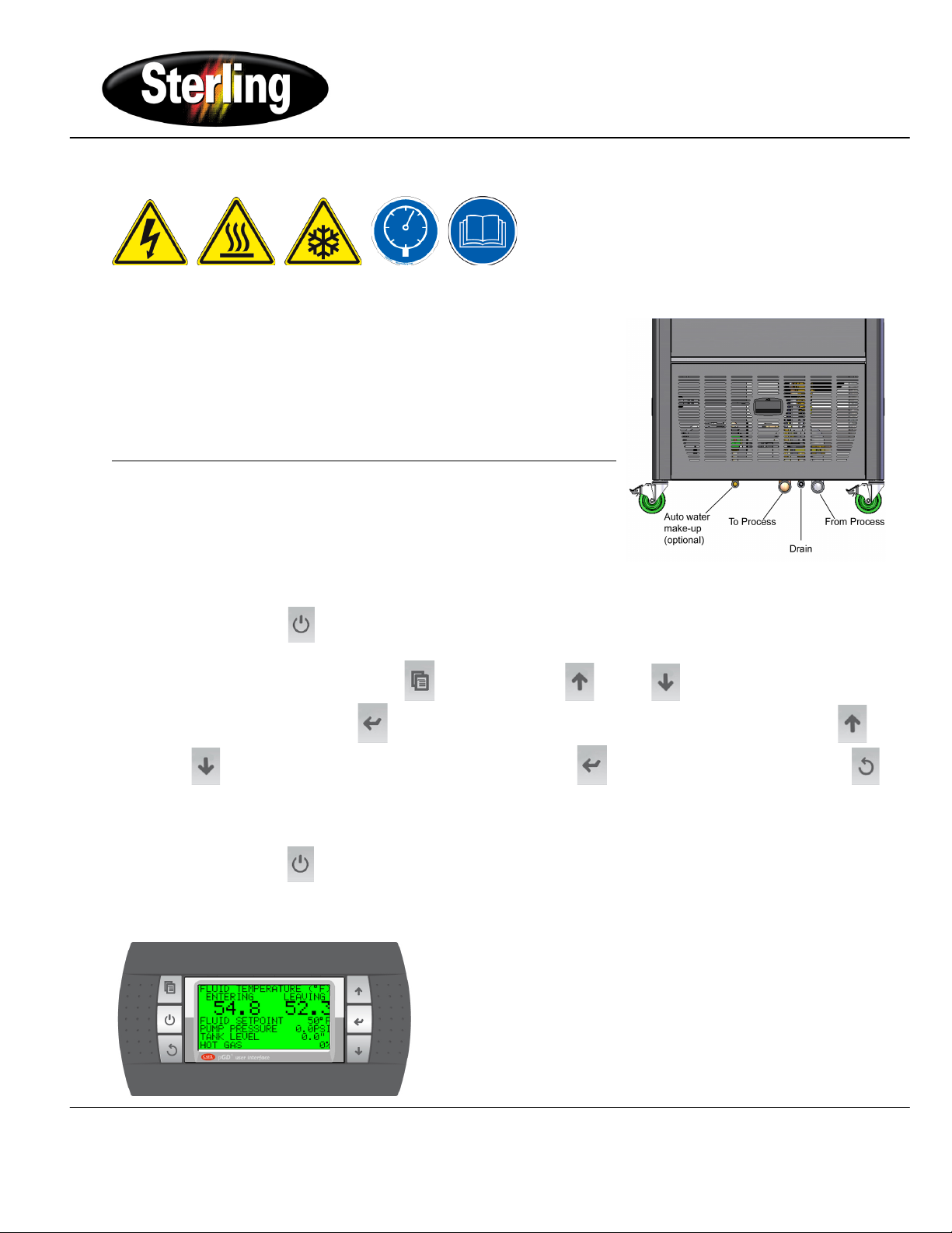
Safety Concerns
Quickstart Installation Checklist
(Refer to main manual for complete installation instructions).
1. Connect 3-phase power based on nameplate data.
2. Apply power to chiller for at least 24 hours prior to start up.
3. Install properly sized plumbing between portable chiller and primary
processing equipment (supply and return).
4. Ensure proper pump rotation. (The pump motor should be turning
clockwise while looking at the motor fan end).
Unit Operation
(Refer to main manual and controller manual for complete operating
instructions).
Start Up
1. Add fluid to the reservoir tank until the level is near the top of the tank.
2. Turn power switch to ON position.
3. Depress the "On|Off" button to start the pump.
4. Maintain the minimum tank level based on size of tank. Handheld display will notify you about tank level.
5. To change the setpoint, press the menu button, press the up or down arrow button to highlight SETTINGS
and press enter. Press the enter button to move the cursor to the CHILLED FLUID SP line. Press the up or
down button to increment or decrement the value. Press enter to accept the value. Press the escape
button twice to return to the main status screen.
Shut Down
1. Depress the “On|Off” button to shut down chiller.
2. Maintain power switch in the ON position.
Standard Display
GP20-50 Series Portable Chillers
Reference Manual (PN: 882.93092.01) for
Complete Operation and Installation Instructions
(Available online at www.sterlco.com)
Sterling, Inc. Part No: 882.93615.06
2900 S. 160th Street • New Berlin, WI 53151 USA Bulletin No: HC3-300.2
Tel. 262.641.8610 •Fax 262.641.8653
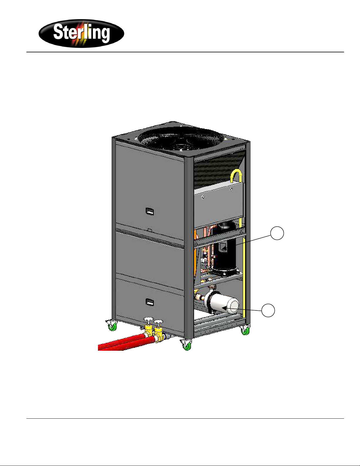
Spare Parts Location
(See next page for Spare Parts List)
1
2
GP20-50 Series Portable Chillers
Reference Manual (PN: 882.93092.01) for
Complete Operation and Installation Instructions
(Available online at www.sterlco.com)
Sterling, Inc. Part No: 882.93615.06
2900 S. 160th Street • New Berlin, WI 53151 USA Bulletin No: HC3-300.2
Tel. 262.641.8610 •Fax 262.641.8653
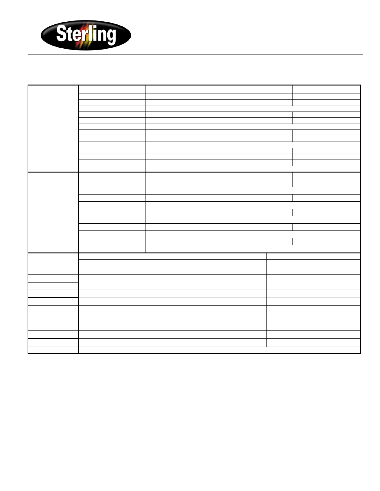
Spare Parts List
(See previous page for Spare Parts Location)
Compressor
208-230/3/60
460/3/60
575/3/50
1
20 kW (5 hp)
Contactor/MCP
726.00332.02
726.00316.02
726.00316.02
Crankcase heater
722.92093.00
30 kW (7.5 hp)
Contactor/MCP
726.00333.02
726.00316.02
726.00316.02
Crankcase heater
722.92094.00
40 kW (10 hp)
Contactor/MCP
726.00333.02
726.00317.02
726.00317.02
Crankcase heater
722.92094.00
50 kW (15 hp)
Contactor
726.00272.02
726.00333.02
726.00332.02
MCP
726.00375.02
Crankcase heater
722.92094.00
Motor Pumps
230/3/60
460/3/60
575/3/50
2
1.5-HP (1.1 kW) MCP
726.00305.02
726.00304.02
726.00303.02
1.5-HP (1.1 kW) Pump Seal
162.00142.01
2-HP (1.5 kW) MCP
726.00306.02
726.00304.02
726.00303.02
2-HP (1.5 kW) Pump Seal
162.00142.01
3-HP (2.2 kW) MCP
726.00306.02
726.00305.02
726.00304.02
3-HP (2.2 kW) Pump Seal
162.00142.01
5-HP (3.7 kW) MCP
726.00316.02
726.00306.02
726.00305.02
5-HP (3.7 kW) Pump Seal
162.00142.01
10-HP (7.5 kW) MCP
726.00317.02
726.00316.02
726.00306.02
10-HP (7.5 kW) Pump Seal
162.00142.04
Common Parts
Pump pressure transducer
733.00117.00
Low Refrigerant Pressure Transducer
733.00112.00
High Refrigerant Pressure Transducer
733.00113.00
High Refrigerant Pressure Switch
733.00103.00
To or From Process Thermistor
701.00213.00
Stainless steel thermistor sensor fitting
053.00051.00
Pendant Display
744.00234.00
10 ft display cable
700.00348.00
Flow switch
735.00109.00
Air Filter – GPAC20, GPAC40
161.01678.00
Air Filter – GPAC30, GPAC50
161.01679.00
AEC Document #

GP20-50 Series Portable Chillers
Reference Manual (PN: 882.93092.01) for
Complete Operation and Installation Instructions
(Available online at www.sterlco.com)
Sterling, Inc. Part No: 882.93615.06
2900 S. 160th Street • New Berlin, WI 53151 USA Bulletin No: HC3-300.2
Tel. 262.641.8610 •Fax 262.641.8653
Troubleshooting - Quick Guide
Problem
Possible cause
Solution
Unit does not run.
No power.
Check main disconnect, fuses, wiring, and
power lead to unit.
Wrong voltage supplied to unit.
Voltage must be within plus or minus 10% of
nameplate rating.
Defective display.
Replace.
Control circuit fuse blown.
Replace control circuit fuse.
Check transformer.
Check for a short circuit.
Defective control transformer.
Replace.
Piping flow switch circuit open.
Add water or water/glycol solution as
required.
Pump motor off on overload.
Reset and test.
Pump runs; compressor does not.
Leaving fluid setpoint set higher than
temperature of liquid in system.
Lower the leaving fluid temperature below the
leaving temperature you desire.
Compressor internal overload or MCP is
open.
Allow time to cool and reset, then check for
high/low voltage. It must be within plus or
minus 10% of the nameplate rating.
Check for open loose compressor electrical
connections.
Failed compressor motor
Compressor contactor holding coil open.
Repair or replace.
Defective compressor auxiliary contact.
Repair or replace.
Broken wire in the compressor control
circuit.
Locate and repair.
Pump runs, compressor cycles at short
intervals.
Plugged Y-strainer
Clean
Hot gas not coming on
Check hot gas analog output value through
status screen. Contact Service if output value
remains at 0% throughout compressor cycle.
Low water flow
Install bypass between to-and-from process
line
Water temperature is too high.
Water/glycol mixture inadequate for
process.
Make sure that the water/glycol mixture
protection is right for the process.
Improperly set leaving fluid temperature,
warning, or fault set point
Adjust.
Refrigerant charge is low.
Call service to find and repair the leak, then
have refrigerant added.
Pump process pressure low (refer to
curves for normal pressure for various
pumps).
Pump running in reverse.
Verify rotation; if running in reverse rotation,
reverse any two main power leads. Re-verify
for correct pump rotation.
Check for foreign matter.
Clean the system strainer.
Pump process pressure is too high.
Restricted water flow.
Check for partially closed valves etc. Make
sure that all lines are properly sized.
Unit runs continuously, but not enough
cooling power.
Restricted condenser air flow.
Clean filters.
Clean condenser.
Unit low on refrigerant.
Check the refrigerant charge by viewing sight
glass on liquid line upstream of the expansion
valve.
Compressor not operating efficiently.
Call service.
Unit under-sized for application.
Call sales rep.
Autres manuels Sterling Refroidisseur


