Telemark TVP-2000 Manuel

Page i of 1
TVP Manual (full) March 2007 CE rev 03.doc
Operation, Installation and Service Manual
Water Vapor Cryotrap
Models TVP-2000 and TVP-3500
Page ii of 2
TVP Manual (full) March 2007 CE rev 03.doc
Tele ark Cryotraps TVP2000/3500

Page 3 of 3
TVP Manual (full) March 2007 CE rev 03.doc
Table of contents
Read this first - Health and Safety advice
Introduction
Section 1 Syste s Operation
1.1. Local ( anual ode using the front control panel)
1.2. Re ote ode operation of a TVP using the 37 pin isolated interface
1.3. Full co puter ode re ote operation using RS232 or other
co unication standard
1.4. Operators quick reference guide
Section 2 Installation Guide
2.0 Unpacking, inspection and installation require ents
2.1 Preparation of cryo-coil and refrigerant lines
2.2 Configuration of re ote interface
2.3 Full co puter ode re ote operation using RS232 or other
co unication standard
2.4 Calibration routine “cal2309”
2.5 Preparation for operation
2.6 Deco issioning
Section 3 Trouble Shooting guide
3.0 TVP 4 essential sub syste s
3.1 Initialisation and start up
3.2 Proble s during cool
3.3 Proble s during defrost
3.4 Interface and re ote control
Section 4 Tables and data
4.10 Description of electrical supplies, and controls electrical and syste
sche atics
4.11 Syste with side panel re oved showing ain sub-syste s
4.20 Interfacing to the TVP
4.30 Principles of operation
4.40 Description of safety syste s
4.50 Cooling curve TVP odels
4.60 The design and place ent of cryo-coils
4.70 Reco ended spare parts list
4.80 Materials safety data sheet
4.90 CE Certification
4.95 Chinese Hazardous Substances Concentration Table
Section 5 Warranty
5.0 Li ited Warranty for Tele ark Water Vapor Pu ps
Glossary

Page 4 of 4
TVP Manual (full) March 2007 CE rev 03.doc
WARNINGS
THE PHRASE WARNING IS USED WHERE THERE IS A HIGH PROBABILITY OF PERSONAL
INJURY OR DEATH SHOULD THE PROVISIONS HIGHLIGHTED BE IGNORED. IT IS THE DUTY
OF BOTH THE INSTALLER/OWNER AND OPERATOR OF THE EQUIPMENT TO BE FAMILIAR
AND COMPETENT WITH THE OPERATION AND USES OF THE PRODUCT. HELP MAY BE
SOUGHT FROM THE MANUFACTURER.
(1) The syste contains specific hazards, which present a significant danger to personal
safety;
(a) high voltage electrical co ponents and high-pressure refrigerant gases, which are
a significant frostbite hazard.
(b) refrigerant gases, which will cause asphyxiation in confined areas.
(c) refrigerant gases, which if exposed to high te peratures deco pose to for very
toxic by-products – never s oke in the vicinity of a TVP or any other si ilar syste
including the gas cylinders.
(d) water in close proxi ity to high voltage electricity.
(e) hot and cold surfaces which represent a significant burn / frostbite hazard.
(2) the syste contains gases under pressure, which ay constitute both a frostbite hazard
and a burn hazard. Refrigerant gases are known asphyxiants and are ildly narcotic.
Precautions ust be taken and work ust only be carried out by suitably qualified personnel.
(3) re oval of any panels other than the front door will expose the operator to high voltage
co ponents, which ay result in a fatal electrocution
(4) failure to leak test the syste as a whole ay result in the catastrophic release of
refrigerant, which presents a very high risk fro frostbite and or asphyxiation. See e ergency
shut down procedures and the aterial safety data sheet for guidance.
(5) during installation there is the potential to be exposed to high voltage co ponents (up
to 400v ac), which ay result in a fatal electrocution.
(6) TVP units ust always be operated with a suitable ground/earth line. Failure to co ply
ay result in fatal electrocution. Never ta per with or re ove any ground/earth connection
fro inside of the achine.
(7) isolate syste before connection. Ensure the connection cable used is co pliant with
local electrical require ents. Cabling within the unit is tri-rated to CSA / UL / CE nor s. There
should be three power wires and one ground wire; there is no neutral line. Feed cable through
gland and ter inate at ain syste isolator, having first re oved the protective cover.
Ground the TVP at pri ary ground point.
(8) failure to replace isolator cover exposes operators to potentially fatal electrocution. It
is essential this pri ary protection always be in place before the syste is energised.
(9) always isolate the syste through the ain circuit breaker before attaching the re ote
control. When in re ote operation take additional care to prevent personal injury,

Page 5 of 5
TVP Manual (full) March 2007 CE rev 03.doc
as viewed from right hand side.
(10) the refrigeration syste contains a ixed blend of refrigerants and polio-ester oil. These
do not present acute health risks it is essential that the following basic precautions are
followed:
(a) always wear eye protection.
(b) always wear surgical type rubber or latex gloves.
(11) the syste contains specific hazards, which present a significant danger to personal
safety
(a) high pressure refrigerant gases, are a significant frostbite hazard.
(b) refrigerant gases will cause asphyxiation followed by death in confined areas.
(c) refrigerant gases, which if exposed to high te peratures deco pose to for very
toxic by-products – never s oke in the vicinity of a TVP or any other si ilar syste
including the gas cylinders.
CAUTIONS
The phrase Caution indicates a risk of da age to the product or associated plant and
achinery if the provisions are not followed carefully.
(1) Tele ark will not be responsible or liable for either direct or consequential personal
injury or loss clai s arising fro the isuse of the product.
(2) Unit contains pressurised gas. Do not open hand valves until syste is connected to a
Cryocoil, which has been checked for leaks. Do not connect the syste to other syste s
unless their design and application has been approved by the anufacturer.
(3) Closure of the hand valves whilst the syste is at cryogenic te peratures ay da age
the valve seats and invalidate the syste s warranty. It ust only be atte pted on a
cryogenically cold syste in the case of an e ergency, which is causing gross leakage fro
the Cryocoil or refrigerant lines.
(4) Do not connect the TVP to an existing Cryocoil without insuring that the Cryocoil will
accept the operating pressure of the TVP syste and that the whole syste has been fully
leak checked. Failure to do so could da age the coil and the vacuu syste .
(5) The Cryocoil should be no less than 1/2 inch or 13 away fro the cha ber wall or
any other object including other parts of the Cryocoil. Failure to co ply will reduce efficiency.
It is bad practice to ount the Cryocoil directly onto a etal plate.
(6) Access to two sides ust be aintained: The front/control panel and the right side
cooling water/refrigerant line/power/re ote control points. No such require ents are
necessary for the left side or back of the TVP unit. Although a clearance of 70 to allow the
door to open fully is required on the left hand side of the unit.
(7) The correct orientation of the flow is essential if the full potential of the unit is to be
realised:
Inlet to coil on the right }
Outlet fro coil on the left }
(8) The TVP is phase sensitive, if connected in the wrong orientation the unit will not
operate correctly. No da age can be caused by incorrect orientation of the phases.
(9) Poor water vapour pu p perfor ance is often caused by poor insulation or by water
collection on the refrigeration lines.

Page 6 of 6
TVP Manual (full) March 2007 CE rev 03.doc
(10) If the lines have visible frosting or water is seen to leak fro the during defrost or
standby, all of the line insulation ust be replaced.
(11) The ost co on cause of syste alfunction are refrigeration leaks. Careful
attention to the integrity of the syste will ensure opti al perfor ance.
(12) Do NOT repeatedly bend the refrigerant line; this will cause leakage and or breakdown
of the insulating aterials.
(13) Always attach the refrigerant line to the feed-through coupling.
(14) Leak checking should always be carried out with a heliu ass spectro eter leak
detector. Any other ethod ay lead to conta ination of the syste , leaks and ulti ately
syste failure.
(15) Detecting leaks without a heliu ass spectro eter is difficult and ti e consu ing for
all but the grossest of leaks. The leak rate should be less than 5 x 10
-8
bar/L/S this is outside
of the detection range of hand held halogen sniffer.
(16) Most leaks are found at the connections of refrigerant lines, pay particular attention to
these areas. It is i portant that these joints are checked regularly throughout the life of the
installation.
(17) Failure to identify and repair leaks before operation will lead to poor perfor ance
syste conta ination and in extre e cases total syste failure. In such cases the Warranty
will be invalidated.
(18) Ensure the Cryocoil is located in a vacuu cha ber and that the cha ber is evacuated
to at least 0.01 Torr or 1 x 10
-2
bar to prevent overheating of the coil fro latent heat.
(19) Before any leaks are repaired the refrigerant ixture ust be drawn back into the TVP
unit. Using an oil free refrigerant reclai unit. This requires an experienced technician.
Details of how this aybe achieved are outside the scope of this anual.
(20) Do not operate the unit if a refrigerant leak is suspected. Be very careful not to pull a
vacuu within the refrigeration lines as this will lead to conta ination of the syste by water.
(21) Failure to adequately insulate and protect refrigerant feed lines and couplings will result
in reduced cryotrap perfor ance, including possible failure of the entire syste .
(22) The syste uses highly stable PT100 sensors, the te perature easure ent syste is
designed for long-ter reliability and stability of te perature easure ent. Inferring vacuu
perfor ance fro the CI/CO values is an unreliable ethod of process deter ination. Direct
easure ent and observation of the vacuu through either an RGA or Penning type gauge
are the only reliable ethods of evaluating the actual process conditions present.
(23) For process safety reasons the interface has the following co and hierarchy:
COOL - Overrides all other actions.
DEFROST - Will revert to STANDBY when co plete.
STANDBY - Default state.
(24) To prevent syste da age check controlling syste s status and the interface is
correctly wired before atte pting to connect to the TVP.

Page 7 of 7
TVP Manual (full) March 2007 CE rev 03.doc
(25) Do not short circuit the 24 V AC supply (pins 35 & 36) against any pin designated as
ground (GND) as this ay da age the low voltage circuitry. The syste is protected by a
anual re-settable 2-A p ther al fuse located on the left hand side of the re ote connector.
Ensure that there is sufficient resistance in any external circuit to prevent this value being
exceeded.
(26) The re ote is fully isolated, there will be a s all AC potential difference above the
chassis ground/earth. It is i portant to understand that switching can only be achieved
against the ground of the re ote interface as opposed to the earth of the unit.
(27) The onboard co puter protects the syste fro isuse therefore it ay not always be
possible to ake the syste functional. You ay need to wait a short ti e before engaging a
different ode.

Page 8 of 8
TVP Manual (full) March 2007 CE rev 03.doc
TELEMARK TVP SERIES
Classically a TVP is used with an evaporative surface (Meisner/cryo-coil), which is located
within the vacuu cha ber. When in this configuration a Tele ark TVP is an ultrahigh
perfor ance vacuu pu p capable of pu ping water vapor and other condensable gases at
speeds far in excess of conventional vacuu pu ps.
Your TVP uses the latest advanced heat exchanger and refrigeration technology to give
industry leading energy and vacuu perfor ance.
A Tele ark TVP couples speed with a sophisticated co puter control package which includes a
si ple and adaptable user interface with isolated interface and RS232 / 485 co s package
as standard.
The ranges of tasks to which your TVP can be applied are not li ited to pu ping water vapor
in vacuu . Many are used as substrate coolers (chuck coolers) or other applications where a
continuous level of high power cooling in the range –100 to –150
o
c is required.
Your invest ent in a Tele ark TVP is backed by a 1-year warranty, which is detailed at the
end of this anual.

Page 9 of 9
TVP Manual (full) March 2007 CE rev 03.doc
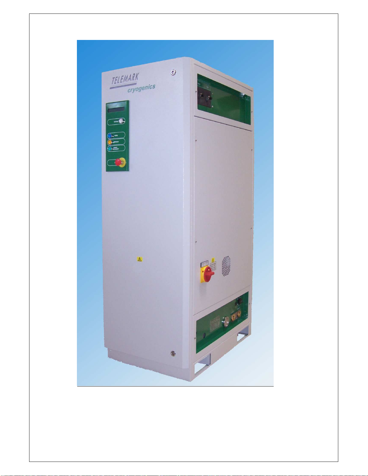
Diagra 1 External view of TVP

Page 10 of 10
TVP Manual (full) March 2007 CE rev 03.doc
Section 1 Syste operation
At any ti e a TVP syste and in any control ode aybe safely turned off by depressing the
stop / e ergency off (EMO) button. (Figure 1)
The following section assu es the syste has been installed correctly and covers the following
odes of operation.
Warning:
Vacuu syste s present any hazards, take ti e to read this anual and fa iliarise yourself
with your installation
1.1 “Local” ( anual) ode using the front control panel
A TVP water vapor cryotrap is fully protected by a sophisticated co puter control syste ,
which allows very si ple anual operation.
The on board co puter protects the syste fro isuse therefore it will not per it operation
when syste para eters are outside acceptable values. Likewise you ay need to wait a
short ti e before engaging a different ode. At any ti e while the syste has power it is
possible to use the scroll button, which re ains illu inated at all ti es.
Diagra 2 The display panel
Display character
ne onic
Meaning Units
DP Discharge pressure Psi
SP Suction pressure Psi
CT Coldest syste te perature (internal easure ent)
O
C
CI Coil in (outlet / flow fro unit) te perature
O
C
CO Coil out (inlet / return to unit) te perature
O
C
CI2 Second coil value – only dual coil units
O
C
E(n) Syste error where n = an integer
Caution
It is good practice to note the balance pressure SP or DP and the coldest te perature CT
before starting the syste after any extended period of shut down as this can pin point a leak
on the refrigeration lines or cryo-coil.
Ce manuel convient aux modèles suivants
1
Table des matières
Autres manuels Telemark Refroidisseur


