Sorotec MINI Control Manuel utilisateur

SOROTEC GmbH
Withig 12
77836 Rheinmünster
Tel.: +49 (0) 7227-994255-0
Fax: +49 (0) 7227-994255-9
E-Mail: [email protected]
Web: www.sorotec.de
Assembly Instruction
Parts kit MINI Control
ETS.MINICONTROL.ESTLSET.01.KO
ETS.MINICONTROL.BEAMSET..01.KO
Version 1.0.0

Page 1/17
Assembly Instructions
MINI Control
www.sorotec.de V 1.0.0
© 2020 Sorotec GmbH
Reprinting, duplication or translation, even in part, is not permitted without the written consent of Sorotec
GmbH. Sorotec GmbH expressly reserves all rights under copyright law.
Technical changes reserved.
Made in Germany.
Technical specications
Main board supply: with external power supplies
Protection class: III (safety extra-low voltage)
Max. main board operating voltage: 36 VDC
Max. sum of the output currents: 2 A
Max. number of axis motors: 3 (with optional extension 5)
Axis motor control: Leadshinepowerampliers
Inputs: 4 x reference input
1 x emergency stop
1 x tool length sensor (probe)
Exits: 2 x transistor output +24 VDC
(fog/oodcooling,Aux),max.each100mA
1 x relay output for spindle potential-free
(FC circuit max 5 A) or +24 VDC, max. 100 mA
1 x fan connector +24 VDC, max. 4 W
Power supplies:
Power supply 1 Plug supply
Input voltage 100 ... 240 100 ... 240 VAC - 50/60 Hz
Max. current consumption (input) 1.9 0.8 A
Power consumption 450 190 VA
Output voltage 36 24 VDC
Max output current 3.7 1 A
Max output power 133.2 24 W
General safety instructions
Only operate the controller indoors. Protect the controller from excessive heat and moisture, including con-
densation.
Do not turn on the controller if you suspect errors or obvious damage. In this case, secure the device against
being switched on again until it is guaranteed to function properly. If in doubt, we will be happy to advise you
at any time - give us a call.

Page 2/17
Assembly Instructions
MINI Control
www.sorotec.de V 1.0.0
Introduction
Thank you for the trust you have placed in us by pur-
chasing the mini controller parts set. Before installa-
tion, we recommend reading through these instruc-
tions completely and then proceeding step by step
as described.
Purpose of use
The set of parts described here is supplied by So-
rotec for the construction of a three-axis control for
CNC machines, especially of the „Hobby-Line“ type.
Any purpose other than that stated is not covered by
the instructions.
Tools needed
Common hand tools such as screwdrivers of various
shapes and sizes, wire cutters, etc. should be availa-
ble. In addition, the following tools are required:
• Wire stripper
• Crimping pliers for ferrules
Danger!
Only carry out the work if you are familiar with the
necessary actions familiar and appropriate
tools are available.
Sorotec GmbH assumes no liability for damage to
property or personal injury occurring during assemb-
ly or operation of the control!
Danger!
The electrical structure described here works in the
low voltage range below 60 volts, which is harmless
to humans. Nevertheless, pay careful attention to
possible sources of error (insulation, grounding, ...)
in order to ensure trouble-free operation. Short cir-
cuits in particular can damage parts of the system or
causeres.
Fig. 1: The parts set for the Mini-Control

Page 3/17
Assembly Instructions
MINI Control
www.sorotec.de V 1.0.0
Scope of delivery
Housing MINI Control 1
Connector panel 1
Stepper motor power
stage 3
Motherboard 1
IO module 1
Drive module 1
Power adapter 1
Plug power adapter 24 V 1
Fan set 1
Main switch 1
Cable gland
M12 11
M16 12
7
8
1
2
3
4
5
6
7
8
10
Rubber foot 4
Adhesive base for
cable ties 8
Cable tie 3,6 x 200 mm 10
Sticker 1
Fuse
2 A slow (T 2A) 18
10 A slow (T 10A) 19
1
1
Wire cable, ready-made
0.5 mm² brown 20
0.5 mm² black 21
2
2
Ground wire
1 mm², 70 mm 1
14-pin ribbon cable
150 mm 1
26-pin ribbon cable
150 mm 1
Ring terminal
1,5 ... 2,5 mm² 5
Jumper 7
USB cable 1
13
14
16
17
22
23
24
25
26
27
9

Page 4/17
Assembly Instructions
MINI Control
www.sorotec.de V 1.0.0
Spacer nut M3
inside outside 18 mm 28
inside outside 20 mm 29
4
10
Spacer nut M3
inside inside 10 mm 17
Pan head screw
DIN 7981 3.5 x 9.5 20
Fan screws
5 x 16 mm 4
Flat headed screw
DIN 7380
M4 x 16 33
M6 x 20 34
1
1
30
31
32
Cylinderhead screw
DIN 7985 M3 x 6 30
Washer DIN 125
Ø M4 36
Ø M6 37
1
1
Toothed washer DIN 6797
Ø M4 38
Ø M6 39
3
3
Nut DIN 934
M4 40
M6 41
2
2
35
Preparing the case
Bottom
For this section you will need: #
1 Housing 1
4 Rubber foot 13
17 Cylinderhead screw M3 x 6 35
17 Spacer nut M3 30
• Glue the four feet 13 ito the corners of the
bottom 1. Lateral distance approx. 5 mm.
• Provide the 17 bottom holes in the rear area of
the housing with spacer nuts 30 and screws 35
(see Figs. 2 and 3). The six bottom holes in the
frontareaareintendedforaretrotoptionand
remain free.
Fig. 2: Bottom of the housing
Fig. 3: Spacer nuts
Page 5/17
Assembly Instructions
MINI Control
www.sorotec.de V 1.0.0
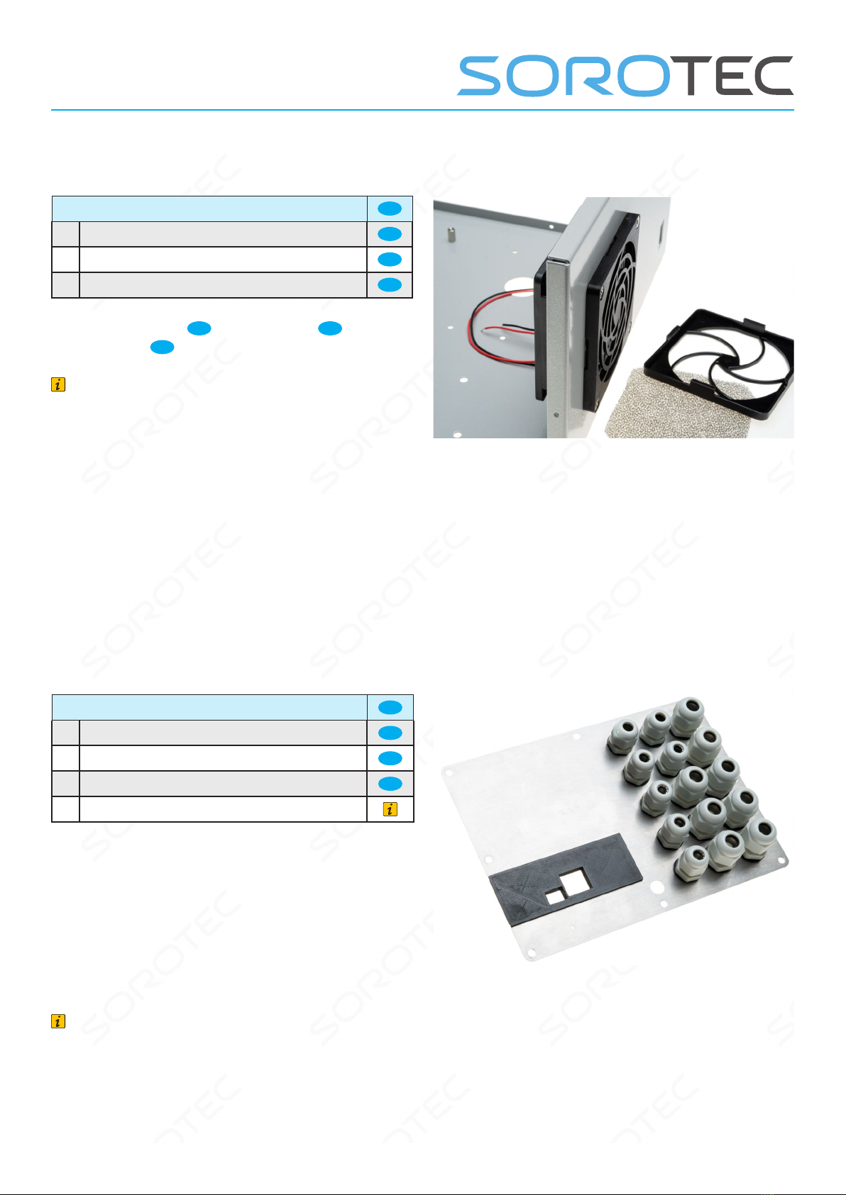
Fan and switch
For this section you will need: #
1 Fan Set 9
4 Fan screw 32
1 Main switch 10
• Mount the fan 9to the housing 1using the
fan screws 32 as shown in Figure 4.
Note
The fan should blow into the case. The ow direc-
tion is marked with an arrow on the edge of the
fan.
• Placetheltereeceonthefancoverand
attachtheltercover.
• Insert the main switch into the rectangular
opening on the front of the housing. The switch
snaps into place and does not need to be
screwed down.
Fig. 4: Fan at the front, cables pointing to the ground
Connector panel
For this section you will need: #
1 Connector panel 1
7 Cable gland M12 11
8 Cable gland M16 12
1 Front cover adapter module
• Install the cable glands in the holes in the
connection panel. The alignment of the nuts is
sometimes important, see also Fig. 15 on page
10.
• Place the 3D-printed front cover that you
received with the adapter module into the cut-out
of the connection panel. See Fig. 5.
Note
The cover is not part of the scope of delivery
for the controller. It is included with the adapter
module.
Fig. 5: Always install unused screw connections as well in
order to close all openings.

Page 6/17
Assembly Instructions
MINI Control
www.sorotec.de V 1.0.0
Functional grounding (FG)
For this section you will need: #
1 Flachkopfschraube M4 33
1 Flachkopfschraube M6 34
1 Scheibe M4 36
1 Scheibe M6 37
3 Zahnscheibe M4 38
3 Zahnscheibe M6 39
1 Erdungskabel 22
2 Mutter M4 40
2 Mutter M6 41
• Remove the paint 2 mm inside and outside
around the holes for the functional grounding
screws (FG).
• Assemble the internal grounding screw
connection from the screw 33 , the washer 36 ,
the toothed washers 38 , the nuts 40 and the
grounding cable 26 as shown in Figs. 6 and 7.
• Assemble the external grounding gland using
the screw 34 , washer 37 toothed washers 39
and nuts 41 as shown in Fig. 8.
Note
The ring cable lugs of ground wires are screwed
between washer and nut as shown in Fig. 7.
Attention!
Make sure there is good electrical contact between
the earthing screw connections and the housing
sheet metal!
Fig. 6: Location of ground connections
Fig. 7: Internal functional ground screw (FG) outside / inside
Fig. 8: External functional ground screw (FG) inside / outside

Page 7/17
Assembly Instructions
MINI Control
www.sorotec.de V 1.0.0
Assembly of the modules
Motherboard („MiniBOB“)
For this section you will need: #
1 Motherboard 4
4 Cylinderhead screw M3 x 6 35
4 Spacer nut M3 x 18 28
2 Spacer nut M3 x 20 29
1Fuse 2 A 18
Note
Before you touch one of the circuit boards, always
rst touch a good conductive earth connection
(e.g. a water pipe) in order to dissipate any static
charge that may be present.
• Assemble the main circuit board 4with
cylinder head screws 35 and the spacers 28
and 29 , as shown in Fig. 9.
• Insert the 2 A fuse 18 into the fuse holder.
Fig. 9: Motherboard
4
18
35
35
28 29
Jumper
• Check the jumpers on the circuit board.
Without using the optional axis extension, the
jumper contacts of CH-A and CH-B should be
unassigned.Ifnecessary,youcanndtheexact
assignment in the option description on page 16.
The jumpers on the main circuit board from top
to bottom (see also Fig. 10 and sheet 4/5 of the
circuit diagram):
1. n/a
2. Probe: Tool length sensor connection to main
board (“MB” for motherboard) or to IO module
(“HomeA”, 4th channel). Default is MB.
3. LPT24: For Beamicon „HomeA“, other „GND“.
4. WDT: not used
5. AUXS: AUX selectable. The default is „OPT2“.
When using the optional IO module FC laser
alarm „OPT1“.
6. ESTOP-Signal: Type of emergency stop
release. For EstlCam and Benezan „H-active“
(default).
Attention!
Correct setting of the jumpers is absolutely essen-
tial for the correct functioning of the control. If you
have any questions, we are happy to answer them
by phone.
Fig. 10: Jumper setting for EstlCam without option modules

Page 8/17
Assembly Instructions
MINI Control
www.sorotec.de V 1.0.0
Antriebsmodul
For this section you will need: #
1 Drive module 6
7 Cylinderhead screw M3 x 6 35
1Fuse 10 A 19
1 26-pin ribbon cable 24
• Mount the drive module 6mit
Zylinderkopfschrauben 35 wie in Bild 11 gezeigt.
• Connect the main circuit board and drive
module with the 26-pin ribbon cable 24 .
• Connect the case fan to the terminal labeled
„Fan“.
• Connect the internal ground wire to one of the
terminals labeled „Shield“.
• Insert the 10 A fuse 19 into the fuse holder.
Fig. 11: Drive module
Note
The connectors of the ribbon cables are with a
central lug secured against unintentionally twisted
insertion. Don‘t force it in!
6
24
19
35
35
Adapter module
For this section you will need: #
1 Adapter module
1 Connection cable
2 Cylinderhead screw M3 x 6 35
2 Spacer nut M3 x 20 29
Note
The adapter module and the matching connec-
tion cable depend on the control software you are
using and are not part of the scope of delivery.
Both Estlcam and Beamicon2 are available for
download from the manufacturers‘ websites.
• Mount the adapter module on the main circuit
board with cylinder head screws 35 and spacer
nuts M3 x 20 29 , as shown in Fig. 12.
• Connect the adapter module and the main
board with the connection cable.
Fig. 12: Montiertes Adaptermodul, hier für Estlcam
Note
The assignment of the cable for the adapter mo-
dules is 1:1. Pin 26 of the Estlcam adapter module
cable is not connected. The corresponding core of
the cable is therefore severed.
35
29

Page 9/17
Assembly Instructions
MINI Control
www.sorotec.de V 1.0.0
Fig. 13: Double spacers
Fig. 14: Mounted IO module
29
29
5
23
IO-Module
For this section you will need: #
1 IO-Modul 5
6Spacer nut M3 x 20 29
1 14-pin ribbon cable 23
• First, screw two more spacer nuts onto the still
open spacer nuts on the main circuit board (next
to the drive module, see Fig. 13), so that the
height is doubled.
• Mount the IO module 5using four additional
spacer sleeves M3 x 20 29 , as shown in Fig. 14.
• Connect the IO2 socket on the main board and
the IO module with the 14-pin ribbon cable 23 .
Note
The space above the IO module is intended for
optional extensions.
Table des matières
Autres manuels Sorotec Système de contrôle


