Sonic immersion iBeam VT300 Manuel utilisateur

Get Ready to Experience
High Definition Bass.


Contents
Items you will need...................................................................................... 4
Introduction & Precautions........................................................................... 5
Specifications.............................................................................................. 6
Home Theater Mounting .........................................................................7 - 8
Home Theater System Connections .............................................9 - 10
Automotive Mounting................................................................................. 11
Automotive System Connections....................................................... 12
Troubleshooting ......................................................................................... 13
Warranty.................................................................................................... 14

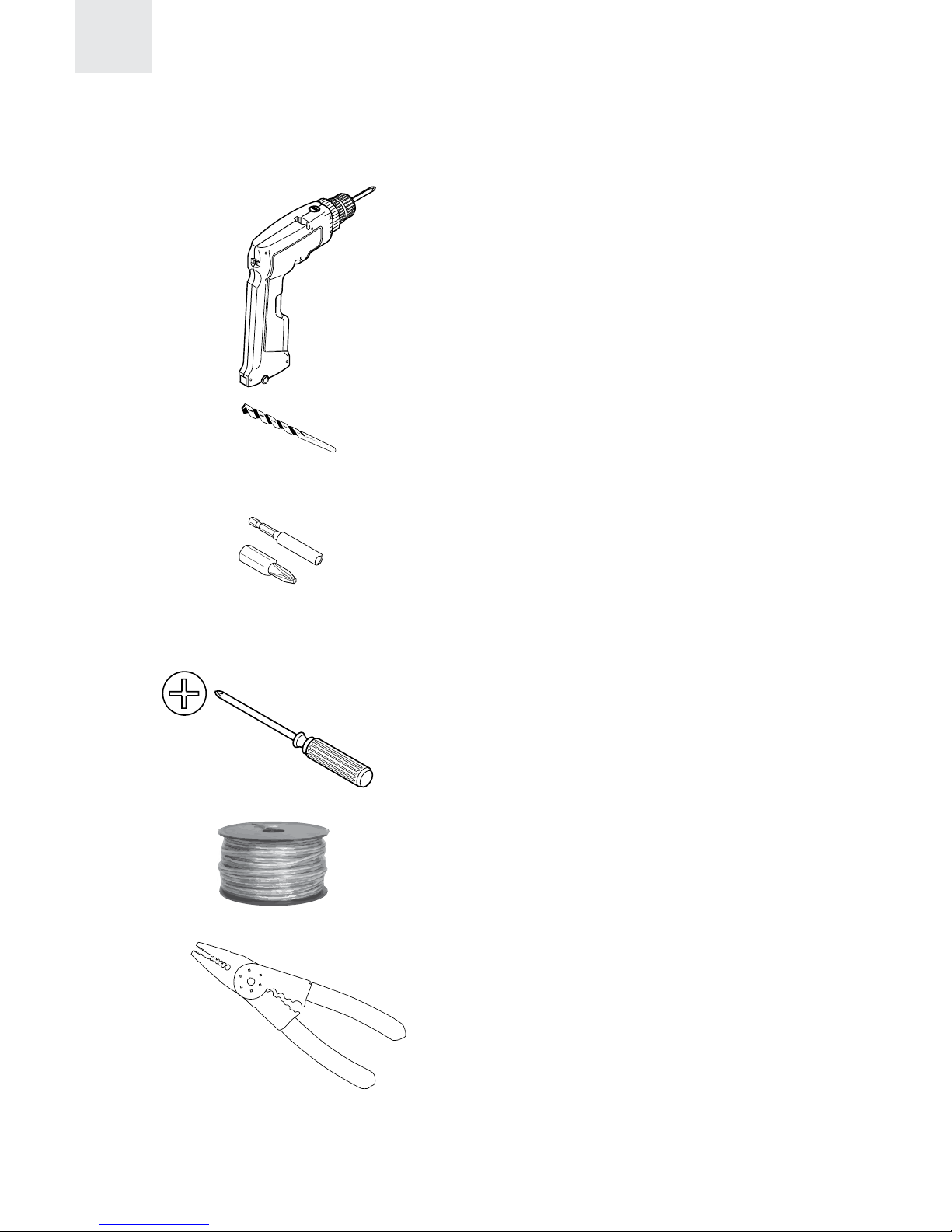
Items you will need
Drill
Drill bit for pilot holes
Phillips head bit w/extension
or
Phillips head screw driver
Spool of 12 or 14 gage speaker wire
Wire strippers ( 12 or 14 gage )
4 5

Introduction and Precautions
I BEAM® Install Guide
1. Welcome
Thank you for purchasing the I BEAM VT300. It represents the new world standard in vibro
tactile transducer performance. The I BEAM delivers powerful deep bass and accurate
broadband sound output. Any sound or movie system will benefit from a properly installed
I BEAM.
2. I BEAM Introduction
The I BEAM produces sound through vibro tactile transfer instead of pressurizing the air around
you. The traditional sub woofer makes sound by “pumping air” with large drivers in a big box.
The I BEAM simulates the excitement of a high volume sound experience without distortion,
noise pollution or ear damage. It literally injects balanced low frequency sound energy into
your body. This energy is delivered so cleanly that the brain interprets the I BEAM as sound,
not shaking. This is why the I BEAM experience is the new world standard in vibro tactile
transducer performance. More information on the I BEAM can be found at www.IBEAMbass.
com. A technical review of the I BEAM design and a comparison of it’s advantages over
available technologies is available at www.IBEAMbass.com/pdf/ibeam_white_paper.pdf
3. Precautions
The I BEAM is a powerful device that must be securely mounted before use! Before
installing the I BEAM read all the instructions provided. Only persons qualified to perform A/V
installations should attempt to install the I BEAM. If any unresolved questions remain after
reading these instructions you can find more installation information on the Install FAQ’S page
When in doubt do not install the I BEAM until comfortable with all procedures and methods
necessary to complete the task.
The I BEAM contains a powerful magnetic motor. Never place tape media or a video monitors
in direct proximity to any large magnet.
4 5

Specifications
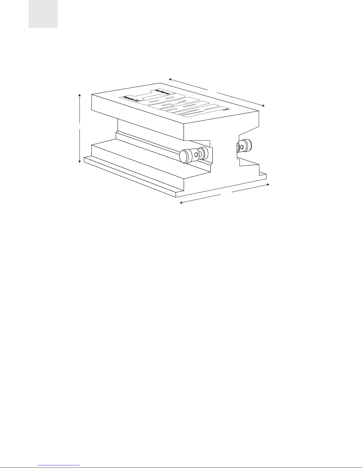
I BEAM®Model # .................................................................... VT300
Size (L x W x H)..................................................6.5” x 4.25” x 2.75”
Weight...................................................................... 3.5 lbs (1.6 Kg)
Maximum Program Force............................... 220 lbs (978 Newtons)
Force / Watt .....................................2.2 lbs/Watt (9.7 Newtons/Watt)
Continuous Power Handling .............................................. 100 Watts
Max Program Power ......................................................... 250 Watts
Overload Protection ........................................... PPTC self reset fuse
Impedance............................................................................ 4 ohms
Frequency Response................................................... 20Hz – 800Hz
Recommended Amplifier Specifications
Any 4 ohm stable amplifier that provides a minimum of 100 Watts RMS is sufficient to
power the I BEAM. Amplifiers 150 – 300 Watts @ 4 ohms offer the finest experience.
2.75”
6.5”
4.25”
6 7

Mounting Guidelines
In many installations the I BEAM can be mounted directly using the 10 built-in through
holes. A universal mount bracket for the I BEAM,SIT part number #UMP1496, is
available when direct mounting is not an option.
Home Theater Seat Mounting
The contemporary Home Theater Seat will generally accept a direct attachment of the
I BEAM using the 10 built-in mounting holes. If your seat was not factory equipped
with the I BEAM it is strongly suggest that you contact the manufacturer directly and
obtain their recommendations for vibro-tactile product mounting.
• Carefully turn the seat upside down. Support it without the possibility of damage
during the installation process. Always use caution when moving Home Theater
Seating as these items can be heavy and somewhat awkward to maneuver. Get
help if necessary.
• Find a location on the seat bottom that allows solid attachment to wood structural
members. The ideal spot is toward the center and rear of the seat bottom. (If
seat bottom mounting is not used choose a location on the seat frame near the
rear and center.) Check for proper clearance from motors and seat adjustment
mechanisms. Try to allow air space between the I BEAM and floor when mounted.
Never use the I BEAM to support the seat.
• Drill pilot holes and secure the I BEAM in the desired location using the supplied
screws. Check for free and complete seat motion. Find another location if the
seat motion is impeded or if seat becomes difficult to move normally.
Secure the I BEAM using the screws in all 10 mounting flange holes.
6 7

Home Theater Seat Mounting
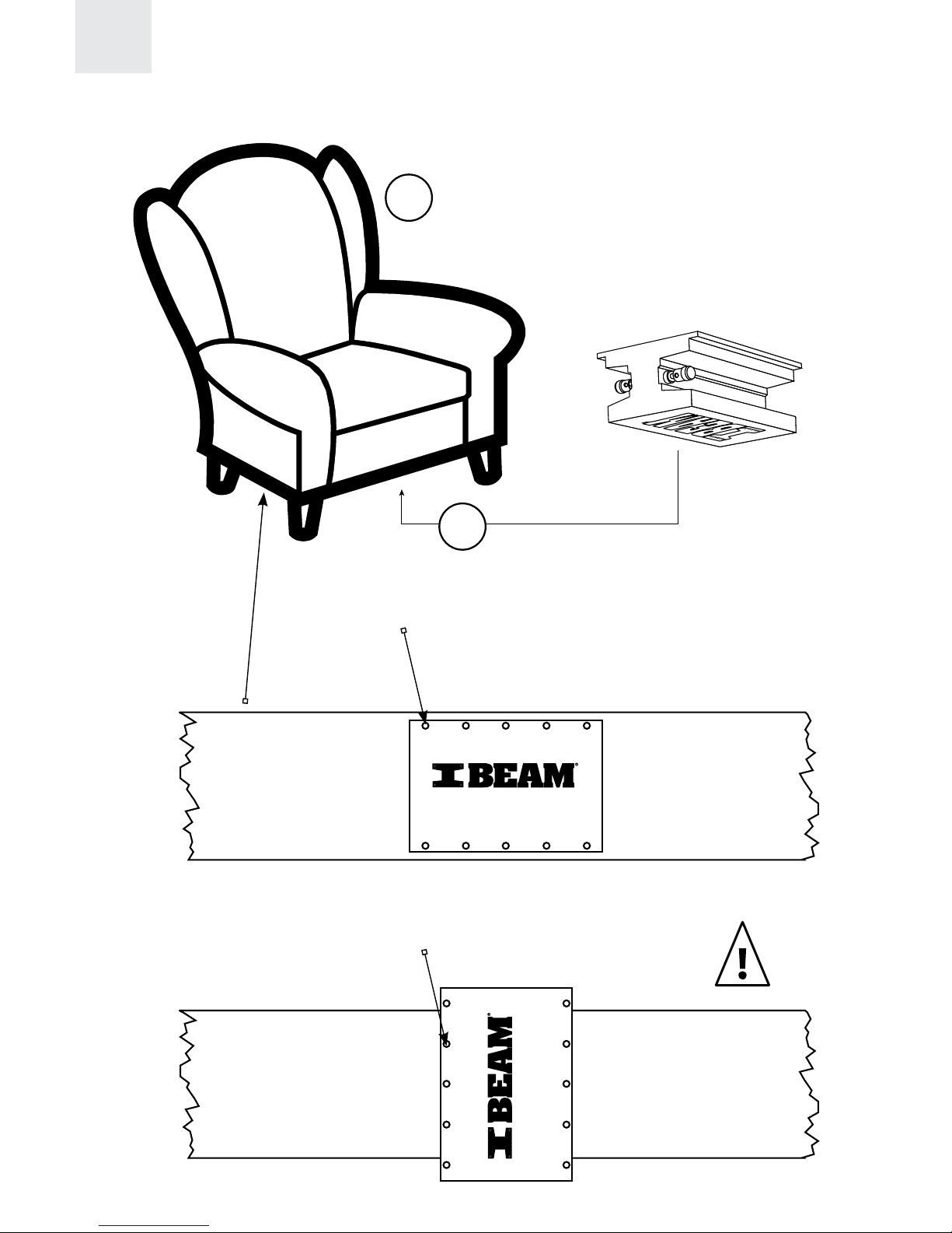
MOUNTING THE I BEAM
Locate solid wood or metal frame underneath couch
or chair. A central location is preferred. Attach the
I BEAM using 10 screws to the frame. A mounting
bracket may be required for some furniture.
Use all 10 screw holes
when mounting long ways.
(Drill Template)
(Drill Template)
Structural support
Structural support
(screws)
(screws) Minimum of 6 screws required
for cross mounting.
1
8 9
1

Home Theater Installation
(Using Sub Woofer Output)
8 9
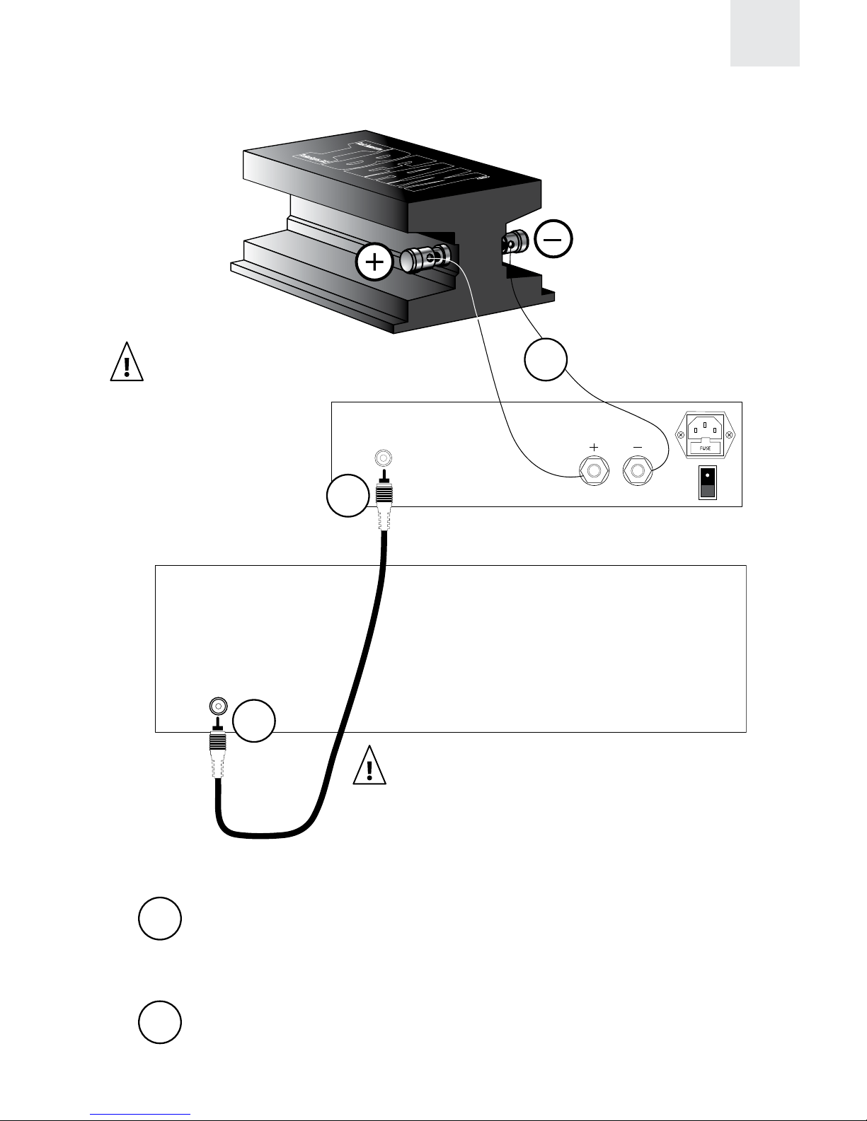
Subwoofer Out
Speaker Output
Line Level
Input
Stereo or
Surround Sound
Processor
Amplifier
Any 4 ohm stable amplifier
that provides a minimum
of 100 watts RMS is
sufficient. Amps 150-300
watts at 4 ohms offers the
finest experience.
It is important that the I BEAM is mounted
correctly for safety and performance.
(Please refer to Mounting Guidelines on page 7.)
Installing the Amplifier
Using RCA cables, connect your sub woofer line out to the
amplifier input. Also be sure your amplifier is plugged in and turned on.
Connect to I BEAM
Attach 12 or 14 gauge speaker wire from the speaker output on
your amplifier to the input terminals on the I BEAM.
1
2
1
1
2

Home Theater Installation
(Without Sub Woofer Output)
Line Out
Speaker Output
Line Level
Input
OPTIONAL CROSSOVER
If your amplifier does not have a built-in crossover, this step may be
necessary. The suggested crossover settings are 100-300hz.
10 11
Harrison Laboratories,
FMOD, 150 LP
Line level output should be controlled by
master volume.
Stereo or
Surround Sound
System
Table des matières
Manuels Transducteur populaires d'autres marques

Mianyang Weibo Electronic
Mianyang Weibo Electronic WB Series Manuel utilisateur

ProMinent
ProMinent Dulcometer DMT Manuel utilisateur

MKS
MKS MicroPirani 925 Series Comment utiliser

WIKA
WIKA WU-20 Manuel utilisateur

Alcatel Vacuum Technology
Alcatel Vacuum Technology BARATRON 622A Manuel utilisateur

Camille Bauer
Camille Bauer SIRAX CH-5610 Manuel utilisateur