Smarteh Longo Modbus Products LMP-1.CA1M Manuel utilisateur

USER MANUAL
Longo Modbus Products
LMP-1.CA1M
Card Access module
Version 1
SMARTEH d.o.o. / Poljubinj 114 / 5220 Tolmin / Slovenia / Tel.: +3 6(0)5 3 44 00 / e-mail: info@smarteh.si / www.smarteh.si

Longo Modbus Products LMP-1.CA1M
Written by SMARTEH d.o.o.
Co yright © 2020, SMARTEH d.o.o.
User Manual
Document Version: 1
January, 2020
i

Longo Modbus Products LMP-1.CA1M
STANDARDS AND PROVISIONS: Standards, recommendations,
regulations and rovisions of the country in which the devices will
o erate, must be considered while lanning and setting u electrical
devices. Work on 100 .. 240 V AC network is allowed for authorized
ersonnel only.
DANGER WARNINGS: Devices or modules must be rotected from
moisture, dirt and damage during trans ort, storing and o eration.
WARRANTY CONDITIONS: For all modules LONGO LMP-1 – if no
modifications are erformed u on and are correctly connected by
authorized ersonnel – in consideration of maximum allowed
connecting ower, warranty of 24 months is valid from the date of
sale to the end buyer, but not more than 36 months after delivery
from Smarteh. In case of claims within warranty time, which are based
on material malfunctions the roducer offers free re lacement. The
method of return of malfunctioned module, together with descri tion,
can be arranged with our authorized re resentative. Warranty does
not include damage due to trans ort or because of unconsidered
corres onding regulations of the country, where the module is
installed.
This device must be connected ro erly by the rovided connection
scheme in this manual. Misconnections may result in device damage,
fire or ersonal injury.
Hazardous voltage in the device can cause electric shock and may
result in ersonal injury or death.
NEVER SERVICE THIS PRODUCT YOURSELF!
This device must not be installed in the systems critical for life (e.g.
medical devices, aircrafts, etc.).
If the device is used in a manner not s ecified by the manufacturer,
the degree of rotection rovided by the equi ment may be im aired.
Waste electrical and electronic equi ment (WEEE) must be collected
se arately!
LONGO LMP-1 com lies to the following standards:
•EMC: EN 61000-6-3:2007 + A1:2011, EN 61000-6-1:2007, EN 61000-
3-2:2006 + A1:2009 + A2: 2009, EN 61000-3-3:2013
•LVD: IEC 61010-1:2010 (3rd Ed.), IEC 61010-2-201:2013 (1st Ed.)
Smarteh d.o.o. o erates a olicy of continuous develo ment.
Therefore we reserve the right to make changes and im rovements to
any of the roducts described in this manual without any rior notice.
MANUFACTURER:
SMARTEH d.o.o.
Poljubinj 114
5220 Tolmin
Slovenia
ii

Longo Modbus Products LMP-1.CA1M
1 DESCRIPTION...................................................................................1
2 FEATURES.......................................................................................2
3 OPERATION.....................................................................................3
3.1 Modbus RTU variables.................................................................4
4 INSTALLATION..................................................................................6
4.1 Connection scheme....................................................................6
4.2 Mounting frame selection............................................................8
4.3 Mounting instructions.................................................................9
4.4 Module labeling.......................................................................10
5 TECHNICAL SPECIFICATIONS................................................................11
6 CHANGES .....................................................................................12
7 NOTES..........................................................................................13
iii

Longo Modbus Products LMP-1.CA1M
1 DESCRIPTION
LMP-1.CA1M RFID reader is intended to be used as an identity verification device at room entrance.
Module also rovides dis lay for four different messages and requests, usually activated from other
module inside the room. This messages are convenient to notify ersonnel (e.g. occu ied, do not
disturb, SOS, room service).
When RFID tag (key-card) is a roached to the reader, the green LED blinks and a short bee is
generated if code is successfully read out. In case key-card for corres ondent room is valid, the
green LED blinks again and a short bee is generated. Other devices can be activated at this event
like door lock o ening, turning light on... If the ID card number is not valid, the red LED blinks and a
longer bee is generated.
In case other (magnet or contact–chi ) card system is used for door unlock, LMP-1.CA1M module can
be used only to show messages.
LMP-1.CA1M module can be modified on customer request: custom front label, touch buttons added,
LEDs added, housing colour. Please contact manufacturer for more information.
LMP-1.CA1M reads unique ID (UID) from standard ISO/IEC 14443 A/MIFARE.
1

Longo Modbus Products LMP-1.CA1M
FEATURES
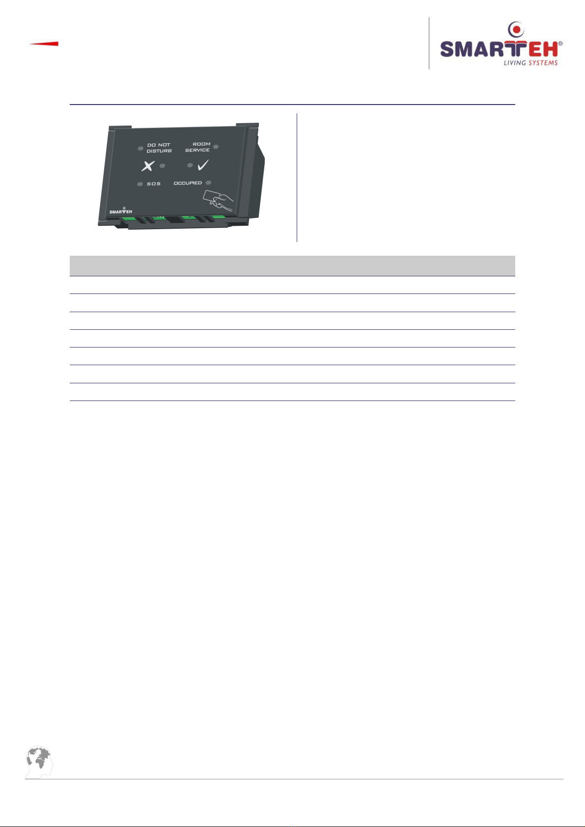
Figure 1: LMP-1.CA1M module.
Table 1: Features
RFID reader
LEDs for showing activated messages & requests: occu ied, do not disturb, room service, SOS
OK “ √ ” LED
FAULT “ X ” LED
Power LED
Internal fault LED
Internal built-in buzzer
2

Longo Modbus Products LMP-1.CA1M
3 OPERATION
O eration of the CA1M module is also de endent on arameters received on Modbus RTU
communication channel.
Reader RFID field is active always when module is owered u . If tag is ut inside RFID field, reader
tries to resolve RFID tag code. If code is read successfully, module activates status iIDNew,
generates a short bee , OK LED4 blinks and code is transmitted in iIDW1 - iIDW4 status fields. In
main module a lication this code can be read out and authenticated. If code has a ro riate
rights, main module should activate idCodeOK command. If code is not authorized, main module
a lication should activate idCodeFault command. Regarding command received, following action
are triggered on module:
idCodeOK ==> OK LED4 blink, short bee .
idCodeFault ==> FAULT LED3 blink, long bee .
Either command is received or not from main module a lication within 10 seconds, module clears
iIDNew status and waits for next RFID tag. While CA1M module is waiting for authorization res onse,
new RFID tags can not be read.
To check if communication is running, master toggles oCommToggleBit and then reads if
iCommToggleBit was toggled.
3

Longo Modbus Products LMP-1.CA1M
3.1 Modbus RTU variables
Do not use oll times smaller than 200 ms and greater than 4 s.
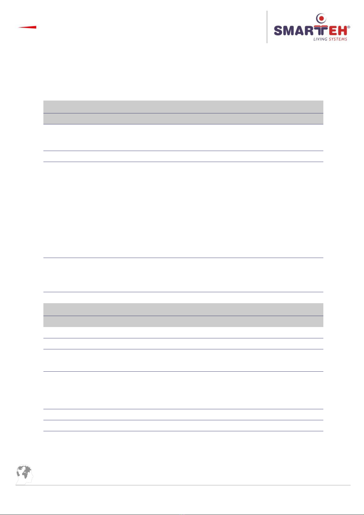
Table : 4xxxx, Holding registers
Reg. Name Description Raw → Engineering data
90 oSaveModbusSettings
Save EEPROM settings; change
the value from 0 to 12345 to
save settings
0, 12345
98 mbSlaveAddressMem Modbus Slave Address 1 .. 247 1 ..247→
99 mbBaudrateMem Modbus Baudrate
1 → 600 b s
2 →1200 b s
3 → 2400 b s
4 → 4800 b s
5 → 9600 b s
6 → 14400 b s
7 → 19200 b s
8 → 38400 b s
9 → 56000 b s
10 → 57600 b s
11 115200 b s→
other → 19200 b s (default)
100 mbParityMem Modbus Parity
0 none→
1 eve→n (default)
2 odd→
other none→
Table 3: 3xxxx, Input registers
Reg. Name Description Raw → Engineering data
1 iIDW1 RFID ID received word 1 0 .. 65535 0 .. 65535→
2 iIDW2 RFID ID received word 2 0 .. 65535 0 .. 65535→
3 iIDW3 RFID ID received word 3 0 .. 65535 0 .. 65535→
4 iIDW4 RFID ID received word 4 0 .. 65535 0 .. 65535→
6 iIDLength Lenght of ID code
0 →ID code not received
4 → 4 bytes
7 → 7 bytes
98 iFWver Software version 0 .. 65535 0 .. 65535→
99 iHWver1 Hardware version 1 0 .. 65535 0 .. 65535→
100 iHWver2 Hardware version 1 0 .. 65535 0 .. 65535→
4

Longo Modbus Products LMP-1.CA1M
Table 4: 0xxxx, Coils
Reg. Name Description Raw → Engineering data
1 oIDNewBee Dis Disable bee when new ID is
detected
0 Enabled→
1 Disabled→
2 oBuzz Set/Reset Buzzer 0 Reset→
1 Set→
3 oIDCodeFault ID code Fault confirm 0 Fault not confirmed→
1 Fault confirmed→
4 oIDCodeOK ID code OK confirm 0 OK not confirmed→
1 OK confirmed→
5 oIDFaultLedCmd Set/Reset Fault LED 0 Reset→
1 Set→
6 oIDOKLedCmd Set/Reset OK LED 0 Reset→
1 Set→
7 oLedOccu ied Set/Reset Occu ied LED 0 Reset→
1 Set→
8 oLedDoNotDisturb Set/Reset Do not disturb LED 0 Reset→
1 Set→
9 oLedRoomService Set/Reset Room service LED 0 Reset→
1 Set→
10 oLedSOS Set/Reset SOS LED 0 Reset→
1 Set→
11 oCommToggleBit Communication toggle bit loo 0, 1
Table 5: 1xxxx; Discrete inputs
Reg. Name Description Raw → Engineering data
1 iCommToggleBit Communication toggle bit loo
indicator 0, 1
2 iIDNew New ID detected 0 New ID not detected→
1 New ID detected→
5

Longo Modbus Products LMP-1.CA1M
4 INSTALLATION
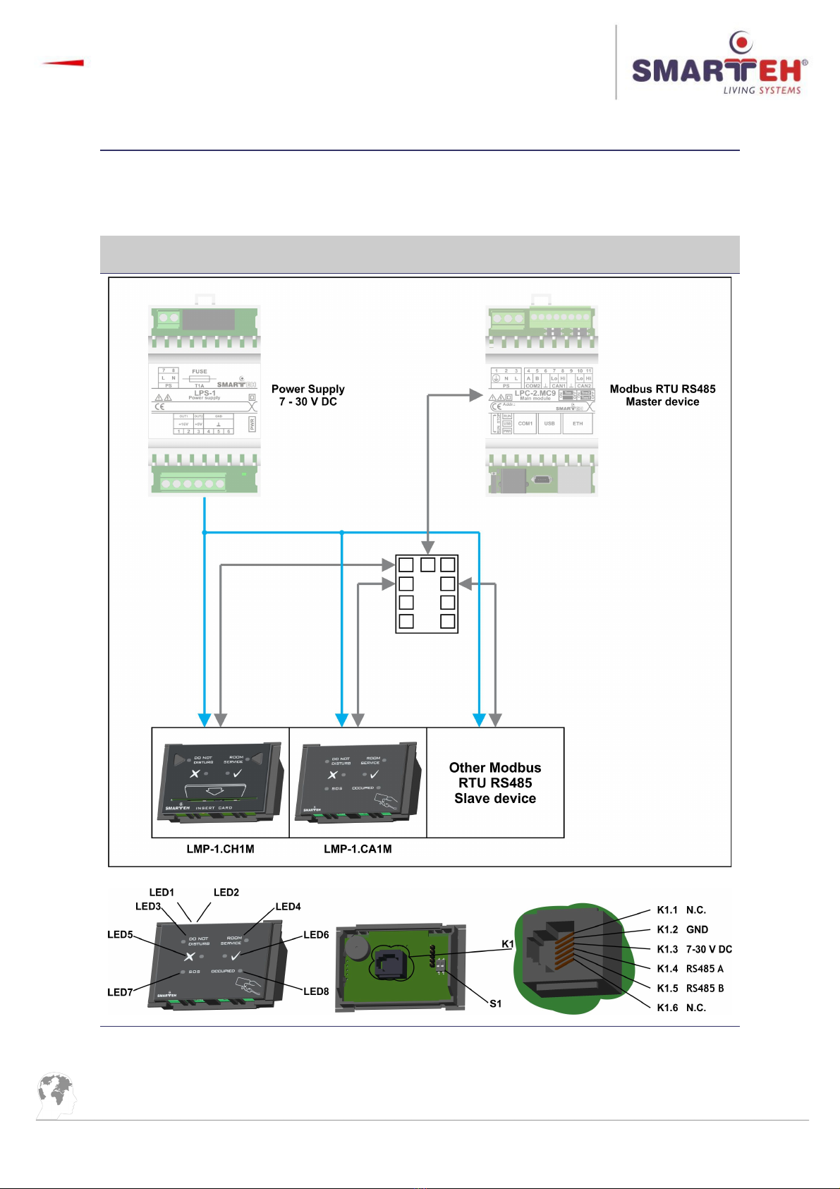
4.1 Connection scheme
Figure : Connection scheme
6
Table des matières
Autres manuels Smarteh Unité de contrôle
Manuels Unité de contrôle populaires d'autres marques

Festo
Festo Compact Performance CP-FB6-E Manuel de la liste des pièces

Elo TouchSystems
Elo TouchSystems DMS-SA19P-EXTME Manuel utilisateur

JS Automation
JS Automation MPC3034A Manuel utilisateur

JAUDT
JAUDT SW GII 6406 Series Guide rapide

Spektrum
Spektrum Air Module System Manuel utilisateur

BOC Edwards
BOC Edwards Q Series Manuel utilisateur