Smart Impulse SMART X Manuel utilisateur
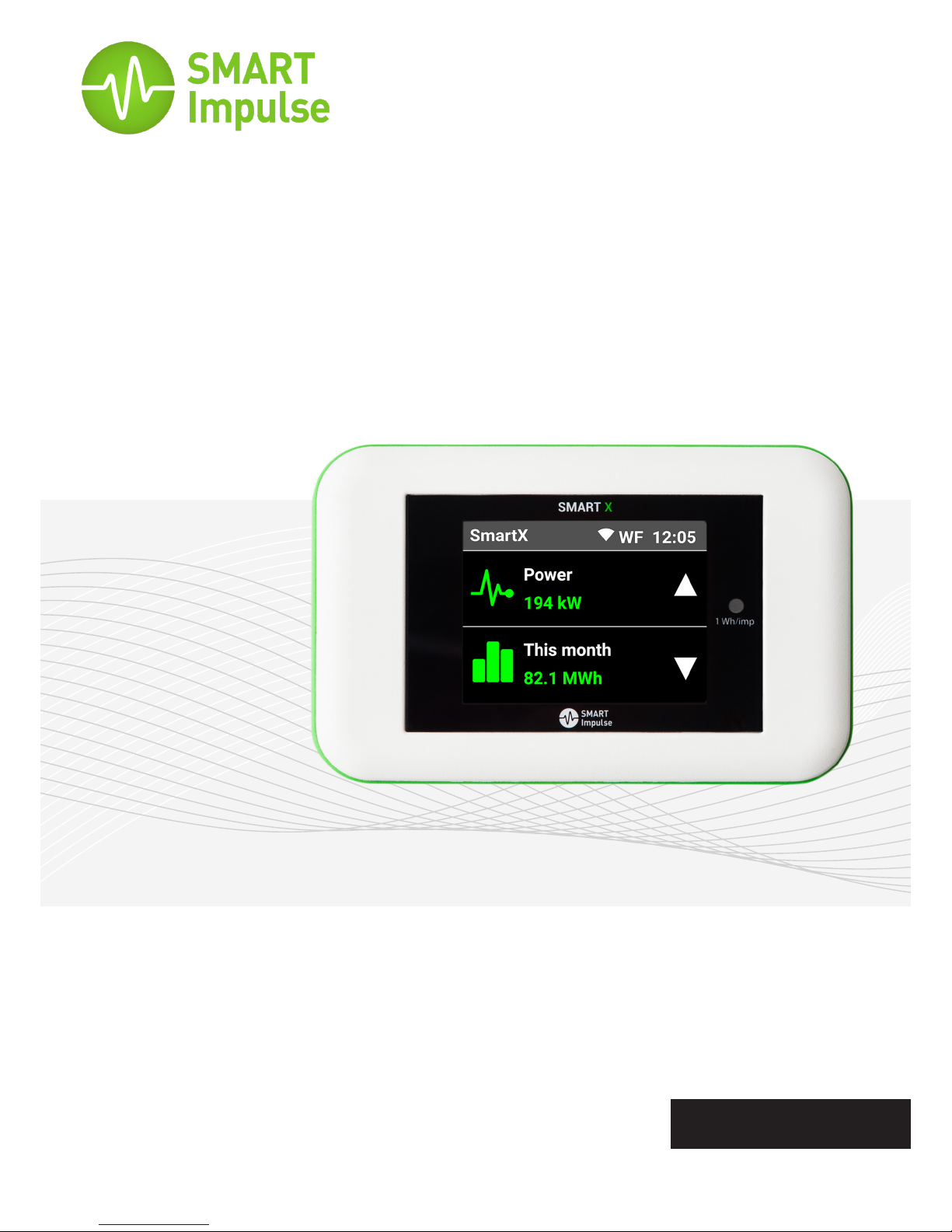
SMART X®
A three-phase power consumption data logger for commercial
and industrial buildings with breakdown by end-use.
Instructions Manual
English
●Read these instructions carefully before installing Smart X.
●The safety of the facilities and buildings where Smart X is installed remains
the responsibility of the assemblers of those systems.
●Smart X must only be handled when wearing personal protective equipment
that is appropriate to protect against (including but without limitation)
electric shocks and falling objects.
●Any installation of Smart X hardware and/or accessories that does not
comply with the specications of this Installation Manual, or with local
regulations regarding electrical installations, will cancel its warranty and may
compromise the safety of the hardware itself, and other equipment and
individuals in proximity.
●For your safety, use only the accessories provided with Smart X or certied
by Smart Impulse, including all sensors and fuses.
●Smart X can be installed on facilities of Installation Category IV,
corresponding to the origin of a building’s electricity supply and its proximity,
for voltage not exceeding 300 VAC compared to the earth (in accordance
with standard EN 60664-1).
INTRODUCTION
WARNING
Smart X® is a device that analyses and identies the power consumption of each type of
equipment in a building, from only one measuring point.
In addition to standard information about the quality of energy, Smart X also provides a
percentage breakdown of electricity consumption by type of equipment or by end-use.
Data measured is retrieved from Smart Impulse servers in real time via an Internet connection,
or at the end of the measurement period when returning equipment to Smart Impulse.
Class II: device fully protected by
reinforced insulation.
2
Symbols used
Warning: instructions must be
consulted each time this symbol
appears.
Warning: potential electric
shock
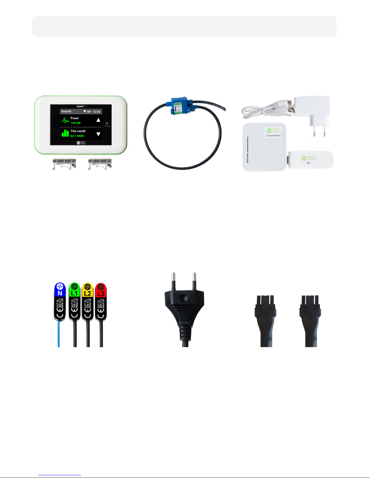
Smart X comes with all of these accessories:
Smart X
Three-phase Lead
Current Sensors
Single-Phase Lead
Smart Router
Bridge Lead
Smart X is the device
that analyses electricity
consumption. It is magnetic
and comes with 2 DIN rail
adapters.
1.5m long, it powers Smart X
and measures three-phase
voltage. Comes with 3 fuse
holders and 4 magnetic
connectors.
Accurate and exible, these
current sensors measure the
3 phases and are universal
(3m or 6m in length; self-
adhesive bases and clamping
clips included).
2m long, it powers Smart X
via an electric socket and
measures single-phase
voltage.
Smart Router is a LAN/3G
gateway that connects to
Smart X via Wi-Fi. It comes
with its own power lead
(3G USB-drive optional) and
adhesive surfaces.
30 cm long, it allows 2 Smart X
devices to share power supply.
3
Contents

TABLE OF CONTENTS
1.
3.
4.
5.
Symbols Used ............................................................................................................ 2
Warning ...................................................................................................................... 2
Contents ..................................................................................................................... 3
Mechanical ............................................................................................................... 10
Power Supply ........................................................................................................... 10
Weather Conditions................................................................................................. 10
Electrical Characteristics ......................................................................................... 10
Standards ................................................................................................................. 10
Communication ....................................................................................................... 11
Data .......................................................................................................................... 11
Mounting .................................................................................................................... 6
Current measurement ............................................................................................. 6
Supply and voltage measurement .......................................................................... 7
Communication ......................................................................................................... 8
Validating installation ............................................................................................... 8
Touch Screen ............................................................................................................. 9
Maintenance ............................................................................................................ 13
Upkeep ..................................................................................................................... 13
Introduction
Characteristics
Instructions
Precautions for safety & upkeep
4
2. Description 5
2
6
10
12
5
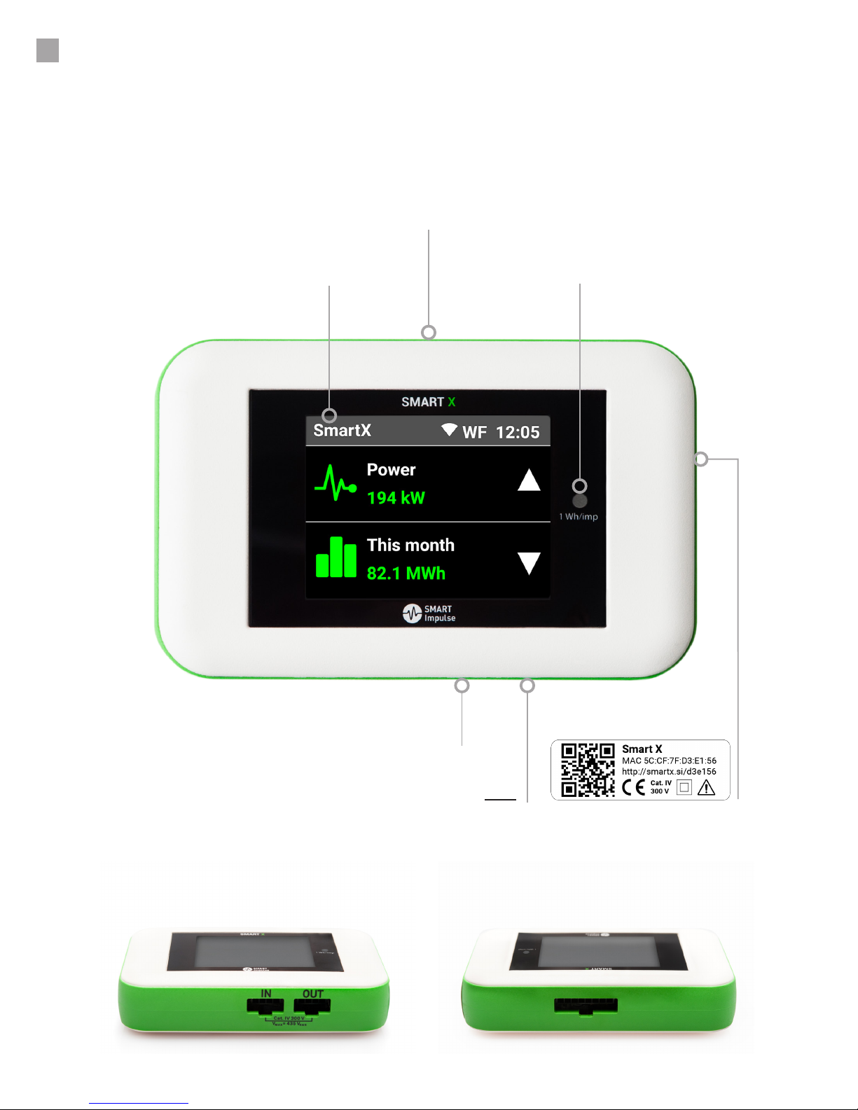
DESCRIPTION
Smart X has three input/output connecting ports:
- 1 input port to connect current sensors (current measurement)
- 1 “IN” port to connect the single-phase lead, or the three-phase lead or the bridge lead (power supply
and voltage measurement)
- 1 “OUT” port to connect the bridge lead (exclusively dedicated to share power supply between
Smart X)
Touch Screen
“IN” port for power supply and voltage
measurement (single-, three-phase or bridge lead)
Input port to measure current
(current sensors)
Metrology LED
(1 Wh/impulse)
Identication Label
“OUT” port for sharing power supply with another
Smart X device (bridge lead only)
View from below View from above
L1-R (phase 1 -green)
L2-S (phase 2 -yellow)
L3-T (phase 3 -red)
NL1 L2 L3
INSTRUCTIONS
6
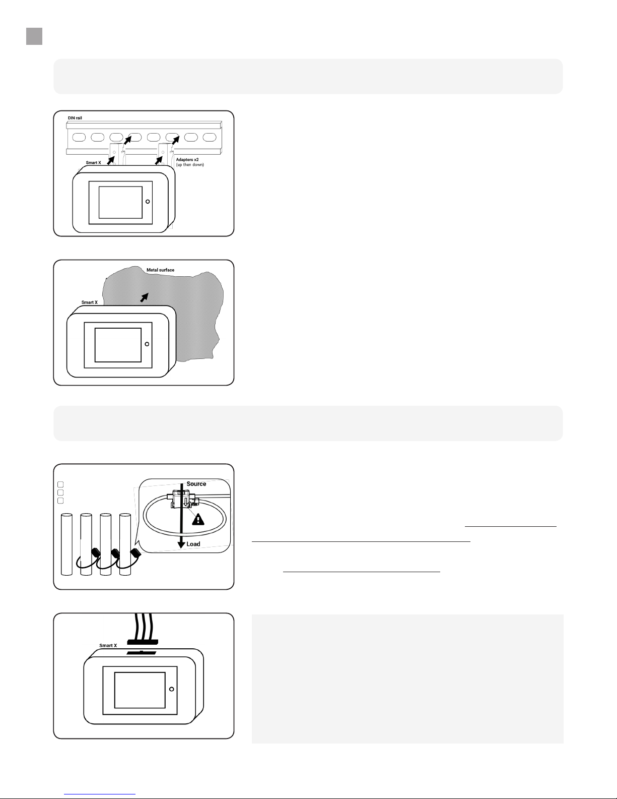
Mounting on DIN rail
Fix magnetic DIN rail adapters to the back of the Smart X
as shown, then x the ensemble to the DIN rail, starting
with the top of the rail rst, then the bottom of the rail.
Mounting
Mounting on a metallic surface
Smart X is magnetic and can be mounted on any metallic
surface.
Current measurement
Position of Sensors
Observations:
- Adhesive mounting bases and clamping clips enable to position the
cables in a neat way.
- If all conductors are not accessible, it is possible to encircle only a
part of them. The number of conductors measured for each phase
must be the same. Imperatively inform Smart Impulse.
- If the electrical panel supplies a capacitor bank or has downstream
power generation units, it is absolutely necessary to measure each of
these points independently using a multi-sensor kit (sold separately).
For each phase of the electrical circuit to be measured
(i.e. main incomer, 3rd oor circuit,…), encircle all insulated
conductors using the split-core sensors, by imperatively
respecting the direction of the sensors (arrows inside
the loop, pointing from the source to the measured
load) and the order of the phases. Then connect current
sensors to the Smart X.
7
IN OUT
Smart X
Fuseholders
Breaker N (neutral -blue)
L1-R (phase 1 -green)
L2-S (phase 2 -yellow)
L3-T (phase 3 -red)
1
STEP
2
STEP
2
STEP
1
STEP
INSTRUCTIONS
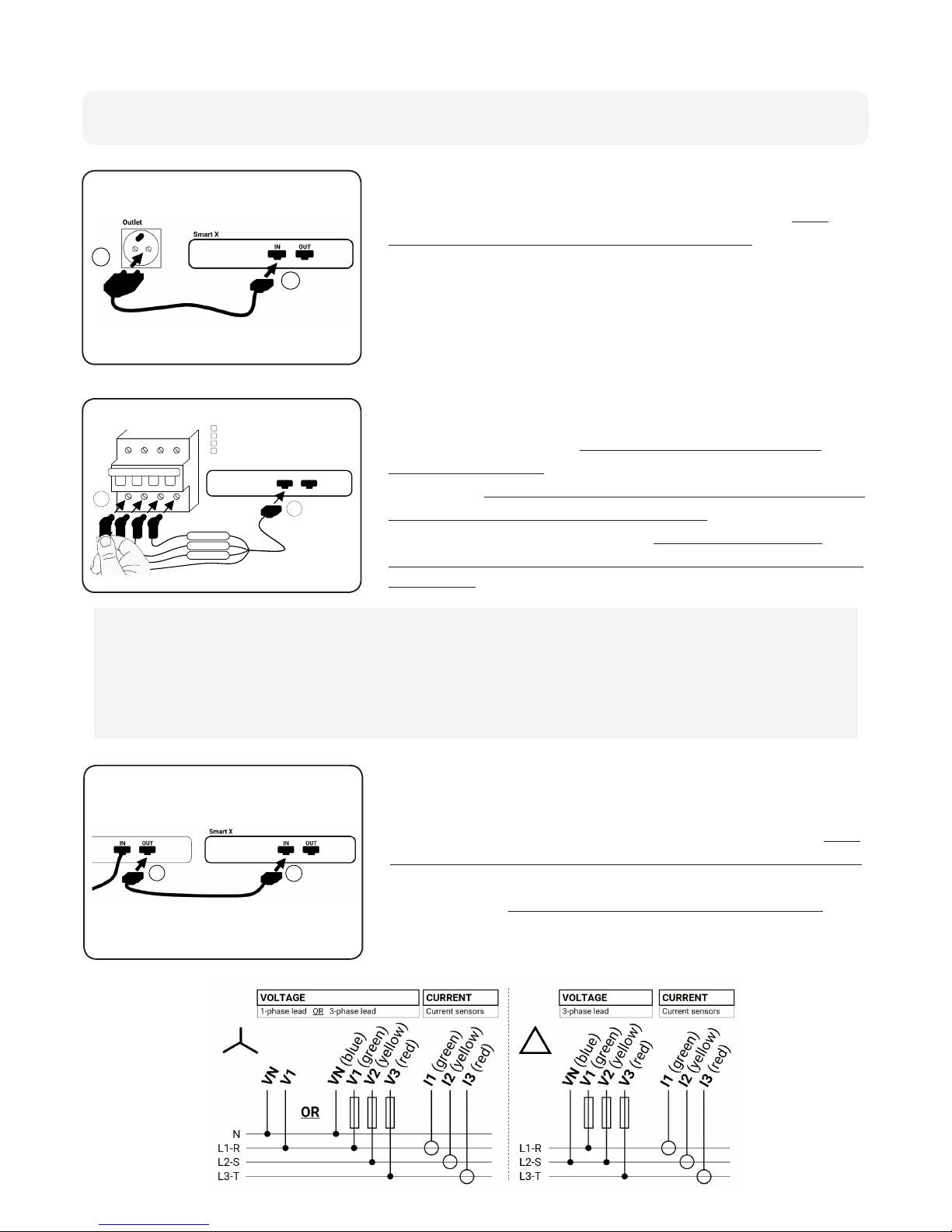
Via a 2-pole socket
Via another Smart X
To measure without opening the electrical panel, rst
connect the single-phase lead to the Smart X (“IN” entry
port), then connect it to a 2-pole socket (a multi-socket
adaptor may be required). In this case, voltage of non-
measured phases will be estimated.
For easy installation, Smart X devices in the same electrical
panel can share the same power supply. In this case, rst
connect the bridge lead to the Smart X that has no power
(“IN” port), then connect it to the Smart X already installed
and powered (“OUT” port, strictly for bridge lead only).
Supply and voltage measurement
Via an existing circuit breaker
For optimum accuracy, rst connect the three-phase
lead to the Smart X (“IN” port), then insert the magnetic
connectors onto the screws downstream of the closest
low voltage modular circuit breaker (accessible through
orices as seen in “2” to the left) while imperatively
respecting the positioning of the neutral and the order of
the phases (max voltage 435 VRMS).
Observations:
- The voltage of circuit breakers in the same electric panel being the same, please connect to the modular
three-phase circuit breaker that is easiest to access.
- If the panel only provides single-phase circuit breakers, connect the neutral and phase 1 of the three-phase
lead to the circuit breaker and connect phases 2 and 3 to the earth.
- If the neutral is not accessible (triangle distribution scheme, ...), connect the neutral from the three-phase
lead (blue lead) to the circuit breaker’s phase 2 (if necessary, strip the lead upstream of the fuses).
1
STEP
2
STEP
8
INSTRUCTIONS
LAN or 3G
Remote Validation
Validation Form
Sigfox
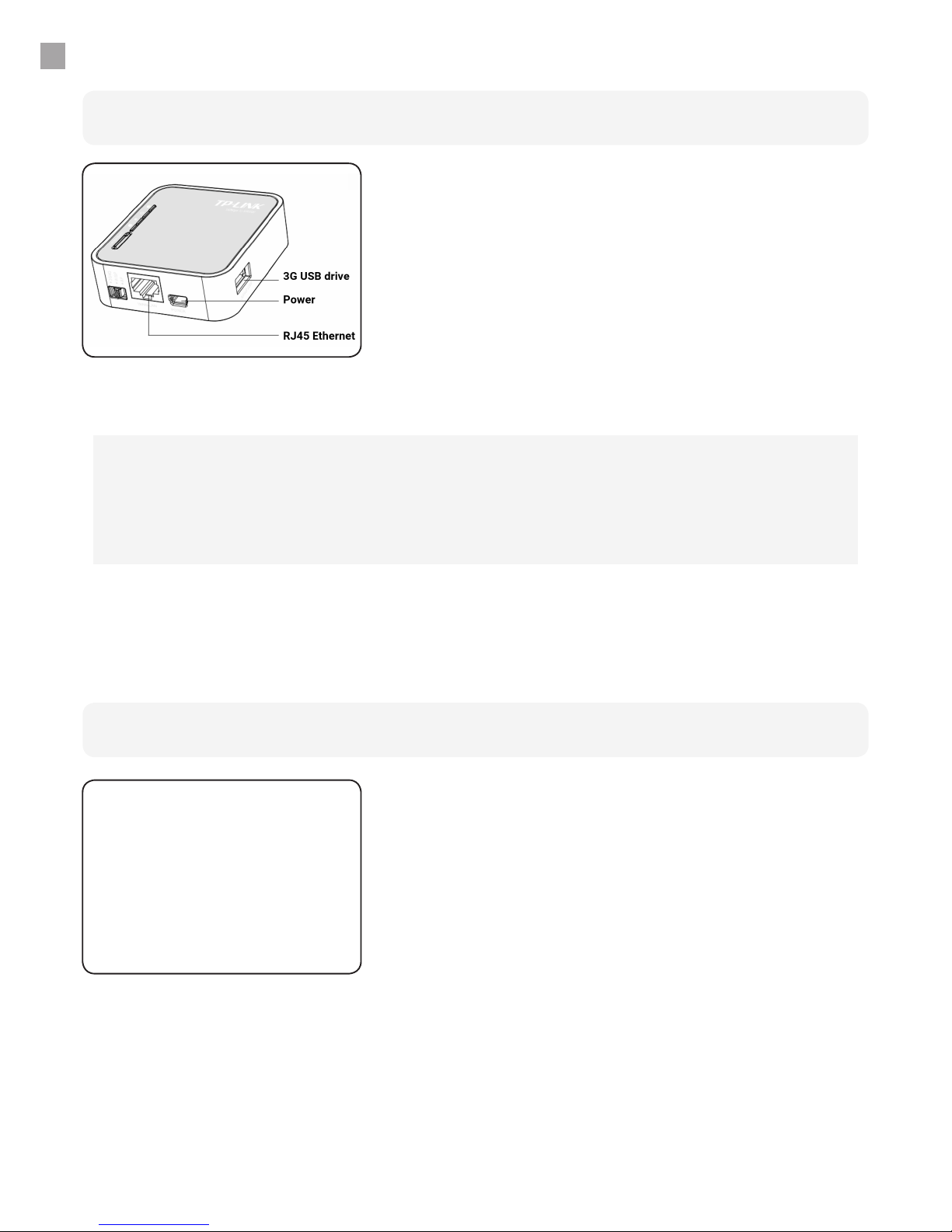
The Smart Router enables the communication of Smart X
data located in the same room to Smart Impulse servers
(up to 15 Smart X devices per Smart Router). To do so,
install the Smart Router close to the Smart X devices
(in the same room), and plug in the Smart Router using
the power lead supplied (a multi-socket adaptor may
be necessary, adhesive mount provided), then connect
it to the local network (LAN) or insert the 3G USB-drive
(optional). After one minute, the Smart X devices will
automatically pair to the Smart Router (WiFi).
Communication
When monitoring only a load curve in a zone covered by
Sigfox, the Smart Router is not necessary: simply follow
the instructions on the screen.
Once installation is complete and has been checked
(direction of sensors, order of phases, coherence of data
appearing on screen), call the Help Desk on
+44 (0) 330 684 6080 to validate the installation.
Within 24h of installation, please send the Installation
Validation Form (available at http://doc.smart-impulse.
required below. Installation is only validated after receiving
these documents.
Required photos: Smart X meter, current sensors, power
supply connection, Smart Router, Wide shot of room after
installation.
Validating Installation
LAN: Before installing, please provide an Ethernet cable and check with your IT department for outgoing
connection authorisation to our server:
- ICMP protocol to 8.8.8.8 (ping), DNS
- TCP protocol to 83.222.241.132, port 80 (HTTP)
- UDP protocol to time.google.com port 123 (NTP)
3G: For optimal data communication, 3G coverage must be greater than -100 dBm. If this is not the case, it is
possible to move the 3G USB-drive. Contact Smart Impulse.
9
Installation
In-use
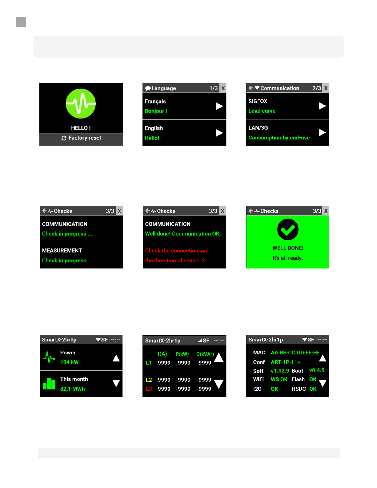
Touch Screen*
INSTRUCTIONS
Language
Select a language. At any
time, touch the “X” (upper
right corner) to close the
installation assistant.
Details
This screen displays the
current and active / reactive
power values measured for
each phase.
Communication
Select desired
communication mode
(Sigfox for load curve
only or LAN/3G via Smart
Router).
System
This screen displays the
state of the Smart X and of
its peripherals.
Starting Smart X
While the meter is starting,
touch the screen to reset
factory default settings
Consumption
This screen displays
instantaneous power and
consumption for the month
in progress.
Verication
During this step, Smart X checks the quality of the connection to the Smart Impulse server and the
apparent compliance of the installation. In the event of non-compliance, actions are proposed.
If a multi-sensor kit is detected, specic actions are proposed.
*depending on version
The Smart X screen switches o (screensaver mode) automatically. Simply touch the screen to activate.
CHARACTERISTICS
Mechanical
Dimensions 117 x 73 x 27 mm (7 DIN modules), protection rating IP20
Mass 175 g not including accessories
Mounting Magnetic for metallic surface or DIN rail with adapters supplied
Power Supply
Source Built-in 2W - Single-phase supply, between blue (N) and green (L1)
leads
Voltage From 50 to 435 VAC between phase and neutral
Typical current
consumed
30 mA at 230 VAC
25 mA at 277 VAC
Electrical Characteristics
Voltage Input Smart X: CAT IV 300 V (source of the installation of the LV* network)
Smart X + three-phase lead: CAT III 300 V (building’s LV* network)
Smart X + electrical socket: CAT II 300 V (LV* network load).
Single-phase with 2 leads or three-phase with 3 to 4 leads, max. volt-
age 435 VAC between leads. Fuse protection 3AG FF 500 mA, breaking
capacity of 50 kA min. Input impedance 330 kΩ (kohm) per phase
Protection rating II. * LV: Low-Voltage
Current Input Three-phase measurement with 3 cables
ATO Sensors: from 0 to 125 AAC, max. diam. 16 mm
ART Sensors: at 50 Hz, max. 2 750 AAC per phase, max. diam. 125 mm
at 60 Hz, max. 2 300 AAC per phase, max. diam. 125 mm
Signals from 0 mVp to 500 mVp, tolerable overload 2 Vp
Frequency 50 Hz ± 0,5 Hz or 60 Hz ± 0,5 Hz
Weather Conditions
Use Indoors
From 0 to 2 000 metres altitude
From 5 °C to 40 °C; 10 % to 80 % relative humidity
Storage Indoors
From 0 to 10 000 meters altitude
From 5 °C to 40 °C ; 10 % to 80 % relative humidity
This product complies with French norms EN/CEI 61010-2-030, EN 61326-1:2013, EN 301 489-1 V2.2.0:2017, ETSI EN
301 489-3 V2.1.1:2017, ETSI EN 301 489-17:2017 V3.2.0, EN 62479:2010, ETSI EN 300 220-2 V3.1.1:2016, ETSI EN 300 328
V2.1.1:2016.
10
Autres manuels pour SMART X
2
Table des matières
Autres manuels Smart Impulse Instrument de mesure


Manuels Instrument de mesure populaires d'autres marques


Endress+Hauser
Endress+Hauser Proline Promag 50 Caractéristiques techniques

Siemens
Siemens SITRANS F Coriolis FCT030 Manuel de la liste des pièces

KLINGER
KLINGER CMF V Series Manuel utilisateur

EXFO
EXFO FTB-2 Manuel d'exploitation et d'entretien

Keysight
Keysight M8290A Manuel utilisateur

ADTEK
ADTEK MW-5 Manuel utilisateur