Sixnet VT-MODEM Manuel utilisateur
USER MANUAL
VT-MODEM
Industrial Modems
Installation & Maintenance
Contents at a Glance:
Section 1 Overview 2
Section 2 Performance Specifications 5
Section 3 VT-MODEM Mounting 6
Section 4 Electrical Connections 7
Section 5 Modem Configuration 14
Section 6 AT Command Summary 18
Section 7 S-Register Summary 21
Section 8 Maintenance Information 23
Section 9 Product Support & Other Documents 24
This manual applies to the following products:
General purpose industrial modem (VT-MODEM-1##)
Self-dialing industrial modem (VT-MODEM-2##)
RS485 industrial modem (VT-MODEM-3##)
VT-MODEM User Manual Page 1 of 30 Last Revised: 17-Aug-09
Sixnet Technology Park 331 Ushers Road Clifton Park, NY 12065 USA +1 (518) 877-5173 [email protected]
Section 1 Overview
The Sixnet VT-MODEMs are rugged industrial telephone modems that have been designed for operation in
electrical enclosures installed in harsh environments. Each VT-MODEM supports all standard Hayes AT
commands, Fax Class 1 and Class 2 commands and S-registers and therefore can be set-up as an external
modem on any PC. The VT-MODEMs are compatible with any telecommunications or dial-up networking
software.
A VT-MODEM allows easy access to PLCs, Sixnet I/O and other devices via dial-in telephone connections.
The modem may be DIN rail or panel mounted for convenient and easy installation adjacent to other DIN
rail components inside of new or existing enclosures. Most Windows software can communicate through a
VT-MODEM to remote devices to perform file transfers, diagnostics, program debugging and many other
operations.
All Sixnet Industrial Modems allow communication to remote sites for data retrieval or diagnostics.
Note: All VT-MODEM models communicate over analog phone lines only.
The Sixnet PLC Self-Dialing Modem (VT-MODEM-2) has all the features of the Sixnet Industrial Modem
(VT-MODEM-1), plus the ability to dial out based on an alarm contact or PLC discrete output.
VT-MODEM User Manual Page 2 of 30 Last Revised: 17-Aug-09
Sixnet Technology Park 331 Ushers Road Clifton Park, NY 12065 USA +1 (518) 877-5173 [email protected]
Identifying the modem you have
This section will show how to identify what revision of modem you have.
1. The Sixnet VT-MODEM Wizard will detect the version of the modem you have. Open the wizard
and detect the modem you are connected to by selecting the COM port your modem is connected to
and clicking the red Detect Modem button on most configuration screens. The firmware version of
your modem is indicated as Rev 1, Rev 2 or Rev 3, otherwise the difference is seamless to the typical
Wizard user.
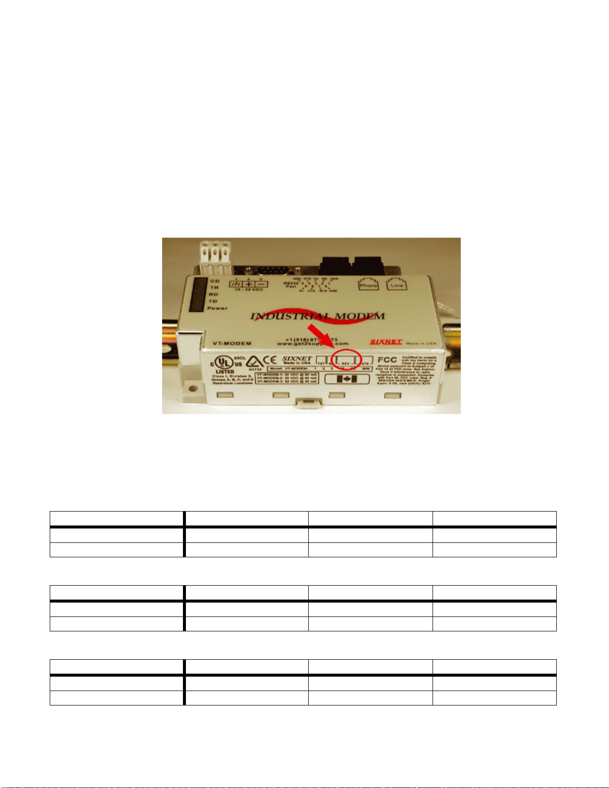
2. On the back of the modem there is a white sticker called the back label that indicates among other
things the revision number (Rev) and modem models. Please see the tables below to see how to
interpret this number.
3. You can also detect the modem type using HyperTerminal. To query the firmware version enter
ati3<enter>. Please see the tables below for information on how to interpret this firmware rev
number.
VT-MODEM-1
VT-MODEM Wizard Rev 1 Rev 2 Rev 3
Back Label 1.00-1.08, 1.10-2.02 1.09 3.00 and above
HyperTerminal (ati3) V2.100-V34_2M_DLS P2109-V90 CX81802-V34
VT-MODEM-2
VT-MODEM Wizard Rev 1 Rev 2 Rev 3
Back Label 1.00-1.04, 1.06-1.08 1.04/1.05 2.00
HyperTerminal (ati3) V2.100-V34_2M_DLS P2109-V90 CX81802-V34
VT-MODEM-3
VT-MODEM Wizard Rev 1 Rev 2 Rev 3
Back Label 1.00-1.02, 1.04-1.06 1.02/1.03 2.00
HyperTerminal (ati3) V2.100-V34_2M_DLS P2109-V90 CX81802-V34
VT-MODEM User Manual Page 3 of 30 Last Revised: 17-Aug-09
Sixnet Technology Park 331 Ushers Road Clifton Park, NY 12065 USA +1 (518) 877-5173 [email protected]

VT-MODEM User Manual Page 4 of 30 Last Revised: 17-Aug-09
Sixnet Technology Park 331 Ushers Road Clifton Park, NY 12065 USA +1 (518) 877-5173 [email protected]
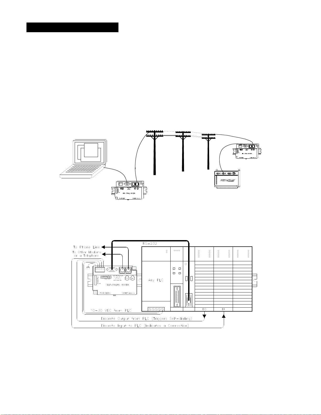
VT-MODEM-2 Self-Dialing Feature
The Self-Dialing Modem is triggered by a switch closure or PLC output signal. It dials a pre-stored phone
number and optionally identifies itself by way of a pre-stored ASCII message. Flexible features allow this
modem to perform retries or even connect to alternate number until it has verified that a connection has been
established. The call will terminate when either:
The computer completes its polling and hangs up
The modem discrete input is turned off
A telephone line problem disrupts the call.
The VT-MODEM-2 enables field installed equipment to establish a telephone link based upon a simple
switch closure. This self-dialing modem adds “dial upon alarm” intelligence to any remote site. This
enhanced modem is ideal for:
DIALING UPON ALARM FROM ANY PLC
This modem establishes a connection based upon a coil output from any PLC. Once a connection has
been established, the PLC’s system (programming) port is connected to the computer at the other end
of the phone link and may be polled by that computer as if the computer had initiated the call. When
the modem connects to the central computer, it identifies itself so the computer can run the
appropriate I/O driver and interrogate the PLC.
SENDING A MESSAGE BASED UPON A SWITCH CONTACT
Locations that do not have PLCs (or other intelligence) can originate calls to alert you to low tank
levels, over temperature conditions, or other alarms. Simply connect the appropriate alarm contact to
the modem’s input. The modem will dial the pre-stored phone number and deliver the ID message to
the computer at the receiving end.
VT-MODEM-3 RS485 Port
The VT-MODEM-3 Industrial Modem Plus has an RS422 / RS485 port that can function in place of its
RS232 port. The RS422 / RS485 port supports RS422 and RS485 full duplex and two wire RS485 half
duplex communication to compatible devices. The VT-MODEM-3 is user-configurable to communicate
through either the RS232 port (VT-MODEM-1 mode) or through the RS422 / RS485 port. Only one port can
be used at a time.
VT-MODEM SETUP WIZARD
A modem setup utility is provided on the Sixnet CD to help you quickly configure any Sixnet Industrial
Modem. In most applications, no knowledge of modem AT commands or S register contents is necessary.
Pre-configured profiles, for common situations are provided for your convenience. An extensive online help
file is provided with this utility.
VT-MODEM User Manual Page 5 of 30 Last Revised: 17-Aug-09
Sixnet Technology Park 331 Ushers Road Clifton Park, NY 12065 USA +1 (518) 877-5173 [email protected]
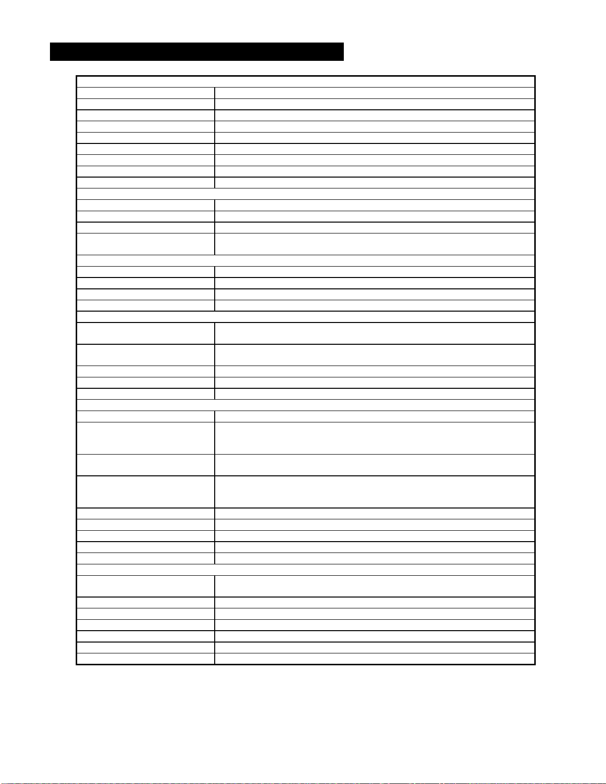
Section 2 Performance Specifications
Telephone Line (All models)
Max. Data Rate 33.6 kbps (V.34)
Compatibility V.34, V.32bis, V.32, V.22bis, V.22A/B, V.23, V.21, Bell212A & 103
Data Compression V.44/V.42bis/MNP 5
Error Correction V.42/MNP 2-4
Max Fax Modem Rate 14.4 kbps (V.33)
Fax Modem Compatibility Group 3 (V.33, V.17, V.29, V.27ter, V.21 ch. 2)
Ringer Equivalent 0.3
Line Jack RJ11
Phone Jack RJ11 (VT-MODEM-1 and –2)
RS232 Port (All models)
Max. RS232 Rate 115.2 kbps (Kilobaud)
RS232 Signal Support TXD, RXD, CTS, RTS, DCD, DTR, DSR, RI, GND
RS232 Connector DB9 female, RS232
Command Set All standard AT and S register commands including Class 1, Class 2 Fax commands
and Voice commands
RS422 / RS485 Port (VT-MODEM-3 only)
RS422 mode 4 wire full duplex
RS485 modes 2 or 4 wire party-line operation (half duplex)
Signal rate Standard rates up to 115.2 kbps (Kilobaud)
RS422 / RS485 distance Up to 0.5 miles
Status LEDs (All models)
CD (Carrier detect) The modem has detected a carrier on the phone line (a remote modem has been
detected).
TR (Data Terminal Ready) The PC (or Gateway/VersaTRAK) has established a connection to the modem and is
ready.
RD (Receive Data) Flashes as data is received from the phone line.
TD (Transmit Data) Flashes as data is sent out the phone line.
Power On when power is present.
General Characteristics (All models)
Input Power 10 - 30 VDC (VT-MODEM-1, –2), 10 – 52 VDC (VT-MODEM-3)
Input Current (Rev 1 and Rev2, see
section 1) 65mA @ 24VDC and 26mA in Low Power mode of –1 (typical)
97mA @ 24VDC and 64mA in Low Power mode of –2 (typical)
68mA @ 24VDC and 28mA in Low Power mode of –3 (typical)
Input Current (Rev 3) 50mA @ 24VDC and 30mA in Low Power mode for -1 and -2 (typical)
55mA @ 24VDC and 35mA in Low Power mode for -3 (typical)
Certification FCC Part 15 and FCC Part 68; UL 508; CSA C22.2/14;
ACA TS 001- 1997; ACA TS 002-1997; AS/NZS3260-1993;
AS/NZS3548-1995; CTR21 (98/482/EC); EN55022; IEC 950:1991.
Operating Temperature -30 ° to 70 ° C
Storage Temperature -40 ° to 85 ° C
Humidity 5 to 95% RH (non-condensing)
Mounting DIN rail or panel mount
Dimensions W x 4.75L x 1.35H inches (8.2 W x 12.1 L x 3.4H cm)
PLC Discrete I/O Interface (VT-MODEM-2 only)
Trigger Input (From PLC) Connects to PLC output. Starts auto-dialing upon transition from OFF to ON. Modem
will stay connected while input is ON.
Voltage Range 9 to 30 VDC
Input Current 6.5 mA at 24 VDC
Max. OFF Voltage 5 VDC
On-line Output (To PLC) Output is ON as long as a connection exists (carrier detect).
Output Characteristics Sourcing – switches supply power
Max. Output Current 100 mA
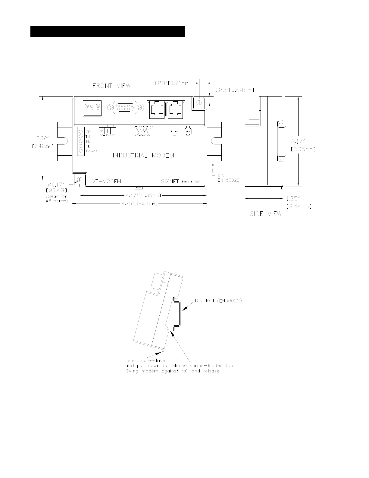
Section 3 VT-MODEM Mounting
The VT-MODEM snaps onto standard DIN rail (DIN EN 50022) or is mounted to a flat panel using #6 or #8
screws. See Figure 3-1. The modem can be installed in any orientation, directly adjacent to other DIN rail
components or in any convenient location within the enclosure. The modem should be installed within 6 feet
of the device it will be connected to.
Figure 3-1: VT-MODEM DIMENSIONS, ALL MODELS
For DIN rail mounting, hook the top, rear of the modem onto the top edge of the DIN rail. Using a small flat
head screwdriver, pull down on the spring-loaded tab on the bottom of the modem and push the modem back
against the rail. Reverse these steps to remove the modem. See Figure 3-2 below.
Figure 3-2: DIN RAIL MOUNTING
VT-MODEM User Manual Page 6 of 30 Last Revised: 17-Aug-09
Sixnet Technology Park 331 Ushers Road Clifton Park, NY 12065 USA +1 (518) 877-5173 [email protected]
Section 4 Electrical Connections
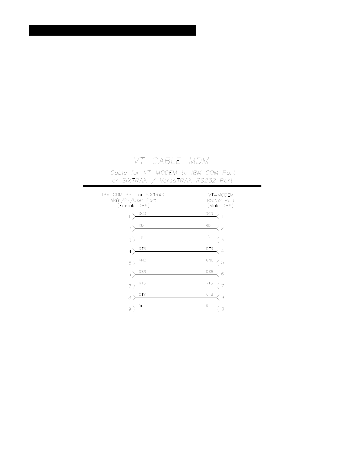
RS232 Connections (All VT-MODEM Models):
Use the Sixnet RS232 cable (VT-CABLE-MDM, which is 6 feet in length) or an equivalent cable to connect
the modem's RS232 port (DB9 Male cable end) to the RS232 port on a SIXTRAK Gateway, VersaTRAK
RTU or PC (DB9 Female cable end). As shown in Figure 4-1, the VT-CABLE-MDM is a straight through
serial communications cable suitable for connecting a DTE device (PC, Gateway or VersaTRAK) to a DCE
device (VT-MODEM). For IPm and ST-GT-1210 stations, use a straight-through Ethernet cable (not
supplied) and the RJ45 to DB9 male adapter that came with the station.
Cable requirements for PLCs and other devices may be different. Refer to the PLC or other device’s
documentation for cable pinouts. Some PLC cables are documented in the Technical notes provided on the
Sixnet CD that came with your modem.
Figure 4-1: VT-CABLE-MDM Wiring
VT-MODEM User Manual Page 7 of 30 Last Revised: 17-Aug-09
Sixnet Technology Park 331 Ushers Road Clifton Park, NY 12065 USA +1 (518) 877-5173 [email protected]
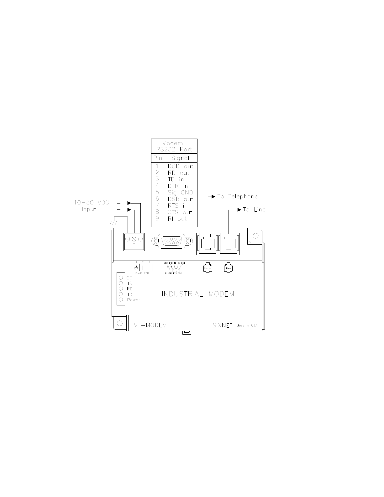
VT-MODEM-1 Power, Phone Line Connections:
DC Power Wiring
Connect 10 - 30 VDC to the VT-MODEM-1 as shown in Figure 4-2. The modem can usually be powered
from the same DC source as other devices in the enclosure. All the screw terminals should be tightened to a
maximum of 3.48 in-lbs.
Telephone Cable
Connect analog phone lines to the RJ-11 jacks as appropriate. One RJ-11 jack is provided to connect directly
to a telephone (optional) and the second RJ-11 jack functions as the connection to the telephone network.
Figure 4-2: VT-MODEM-1 WIRING
VT-MODEM User Manual Page 8 of 30 Last Revised: 17-Aug-09
Sixnet Technology Park 331 Ushers Road Clifton Park, NY 12065 USA +1 (518) 877-5173 [email protected]
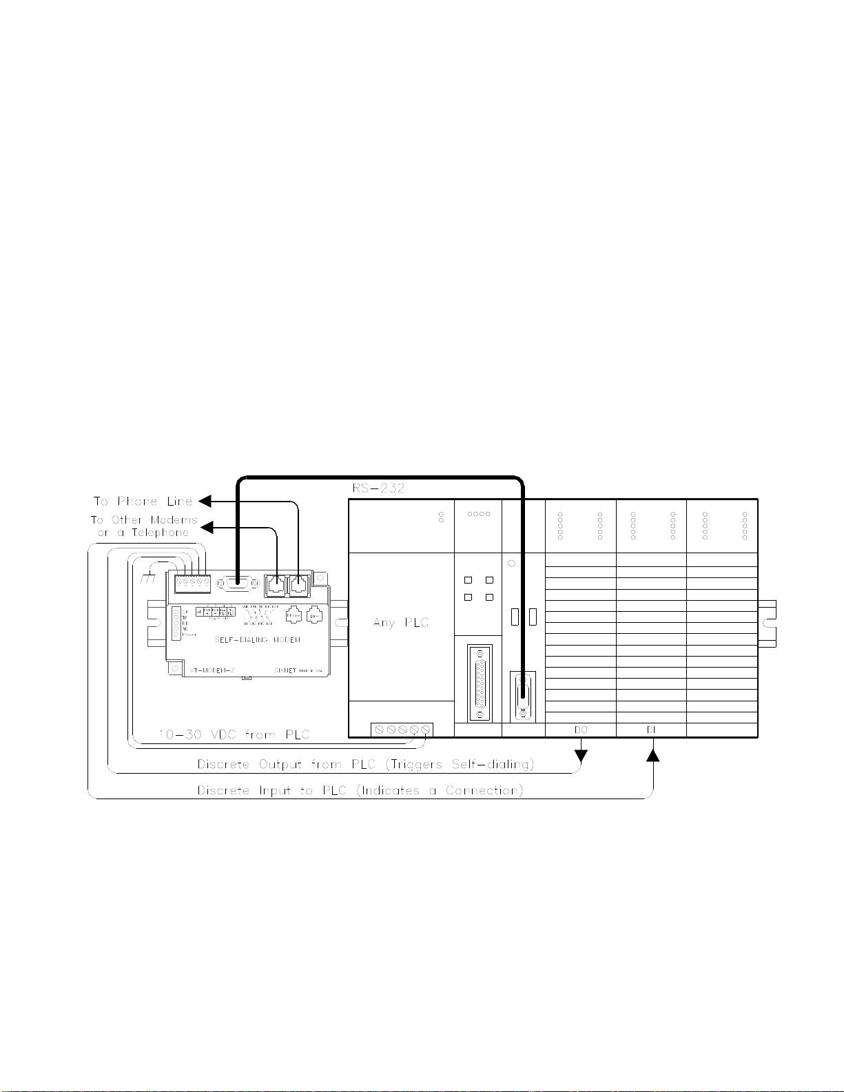
VT-MODEM-2 Power, Phone Line, Self-Dial Connections:
DC Power Wiring
Connect 10 - 30 VDC to the VT-MODEM-2 as shown in Figure 4-3. The modem can usually be powered
from the same source as other devices in the enclosure. All the screw terminals should be tightened to a
maximum of 3.48 in-lbs.
Telephone Cable
Connect analog phone lines to the RJ11 jacks as appropriate. One RJ-11 jack is provided to connect directly
to a telephone (optional) and the second RJ-11 jack functions as the connection to the telephone network.
PLC Self-Dial I/O Connections
Connect a 10-30VDC signal to the ‘From PLC’ (trigger input) terminal. An OFF to ON transition of this
signal starts the auto-dialing sequence. The modem will call and remain connected while the signal is ON.
When the signal goes false, the modem will terminate the connection or the call in progress.
The ‘To PLC’ (on-line output) terminal will go ON (ON = user supplied VDC input) when a modem to
modem connection has been established and the proper ‘Acknowledge Message’ has been received.
Figure 4-3: VT-MODEM-2 WIRING
VT-MODEM User Manual Page 9 of 30 Last Revised: 17-Aug-09
Sixnet Technology Park 331 Ushers Road Clifton Park, NY 12065 USA +1 (518) 877-5173 [email protected]
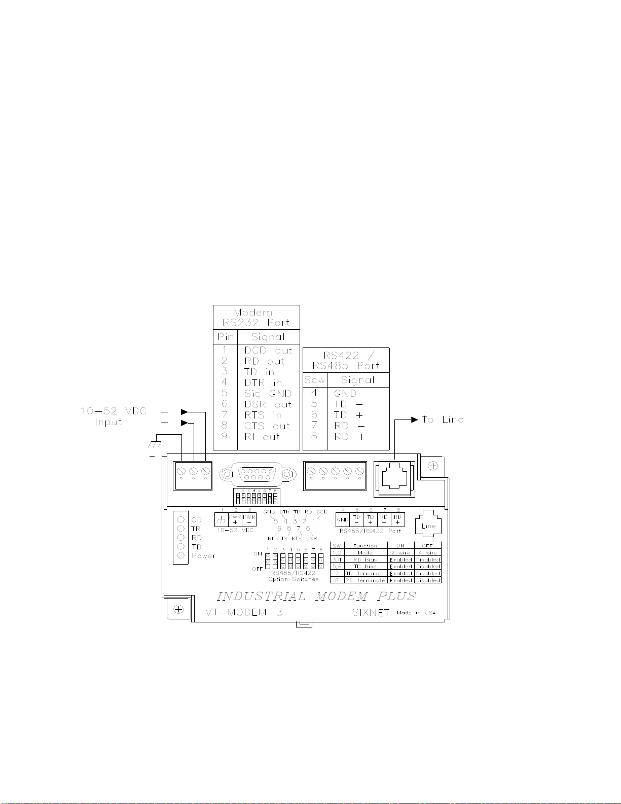
VT-MODEM-3 Power, Phone Line, RS422 / RS485 Connections:
DC Power Wiring
Connect 10 - 52 VDC to the VT-MODEM-3 as shown in Figure 4-4. The modem can usually be powered
from the same source as other devices in the enclosure. All the screw terminals should be tightened to a
maximum of 3.48 in-lbs.
Telephone Cable
Connect an analog phone line to the RJ-11 jack as appropriate.
RS422 / RS485 Cabling and DIP Switch Settings
Refer to Figure 4-4 for typical wiring configurations. Fabricate a cable to connect the modem's RS422 /
RS485 port to the field device(s).
The VT-MODEM-3 has DIP switches. These switches establish the mode of operation for the RS422/RS485
port. Set these switches to match the type of wiring connected to the RS422/RS485 port. Refer to Figure 4-5
on the next page. It is not necessary to cycle power to the modem if DIP switch changes are made.
Figure 4-4: Typical RS422 / RS485 Wiring
VT-MODEM User Manual Page 10 of 30 Last Revised: 17-Aug-09
Sixnet Technology Park 331 Ushers Road Clifton Park, NY 12065 USA +1 (518) 877-5173 [email protected]
Ce manuel convient aux modèles suivants
3
Table des matières
Autres manuels Sixnet Modem


Manuels Modem populaires d'autres marques

Davicom
Davicom DM562AP Manuel utilisateur

EpiValley
EpiValley TATA indicom SXC-1080 Manuel utilisateur

Zte
Zte WiMAX Manuel utilisateur

Intelimax
Intelimax MA-2060 Manuel utilisateur

SMC Networks
SMC Networks D3CM1604V Manuel d'utilisation et d'entretien

Telstra
Telstra Wi-Fi 4G Advanced Pro X Manuel utilisateur


US Robotics
US Robotics 3453C Manuel utilisateur

MaxTech
MaxTech Plug & Play Internal Voice/FAX/Data/SVD... Manuel utilisateur

Zte
Zte MF823 Manuel utilisateur

Four-Faith
Four-Faith F1403 Manuel utilisateur

Sierra Wireless
Sierra Wireless AIRLINK MP595W Manuel utilisateur

Gemtek
Gemtek WiMAX WIXFBR-103 Manuel utilisateur