SITEP PR50 Manuel utilisateur

INSTRUCTION
MANUAL
WATER CHILLER
MODEL PRR 50(N)
27 December, 2002 I:\WP51\MANUALS\water cooler PRR50N-c.wpd

Index:
General information page 1
Water Cooler and its components page 2
(Chap. 1) Useful information page 3
(Chap. 2) Working cycle page 4
(Chap. 3) Location and installation guide page 7
(Chap. 4) Technical data page 8
(Chap. 5) Movement and transport page 9
(Chap. 6) Installation and Final test page 10
(Chap. 7) Putting into use page 11
(Chap. 8) Maintenance and Service page 12
Customer Fault Finding page 13
Electric circuit page 14
Decibel Output page 14
Risks Page 15
Parts Diagram Page 16

Page 1
GENERAL INFORMATION.
THIS MANUAL IS TO BE CONSIDERED AS AN INTEGRAL PART
OF THE MACHINE AND MUST BE CONSERVED WITH THE
MACHINE THROUGHOUT ITS WORKING LIFE.
Before carrying out any operation, it is important to read this instruction manual
thoroughly, particularly the section concerning risk(see page 15).
This manual should be kept in a way so that it is available for consultation at any
time and kept so that it is not damaged ( ie. protected from chemicals, humidity,
dust, sunrays, etc.).
The manufacturer has the right to modernise production of the instruction manual
without any obligation of modernising previous production of this manual.
The manufacturer is not responsible for any malfunctioning of the machine caused
by:
* Irrational, improper and erroneous use of the machine
* Contrary use (Contrary to the operation as stated in this manual)
* Incorrect installation
* Faulty power supply to the machine
* Lack of maintenance as prescribed by the manufacturer
* Modifications or unauthorised interferences
* Use of spare parts which are not original or specified for this model
* Non-adherence of the instructions contained in this manual
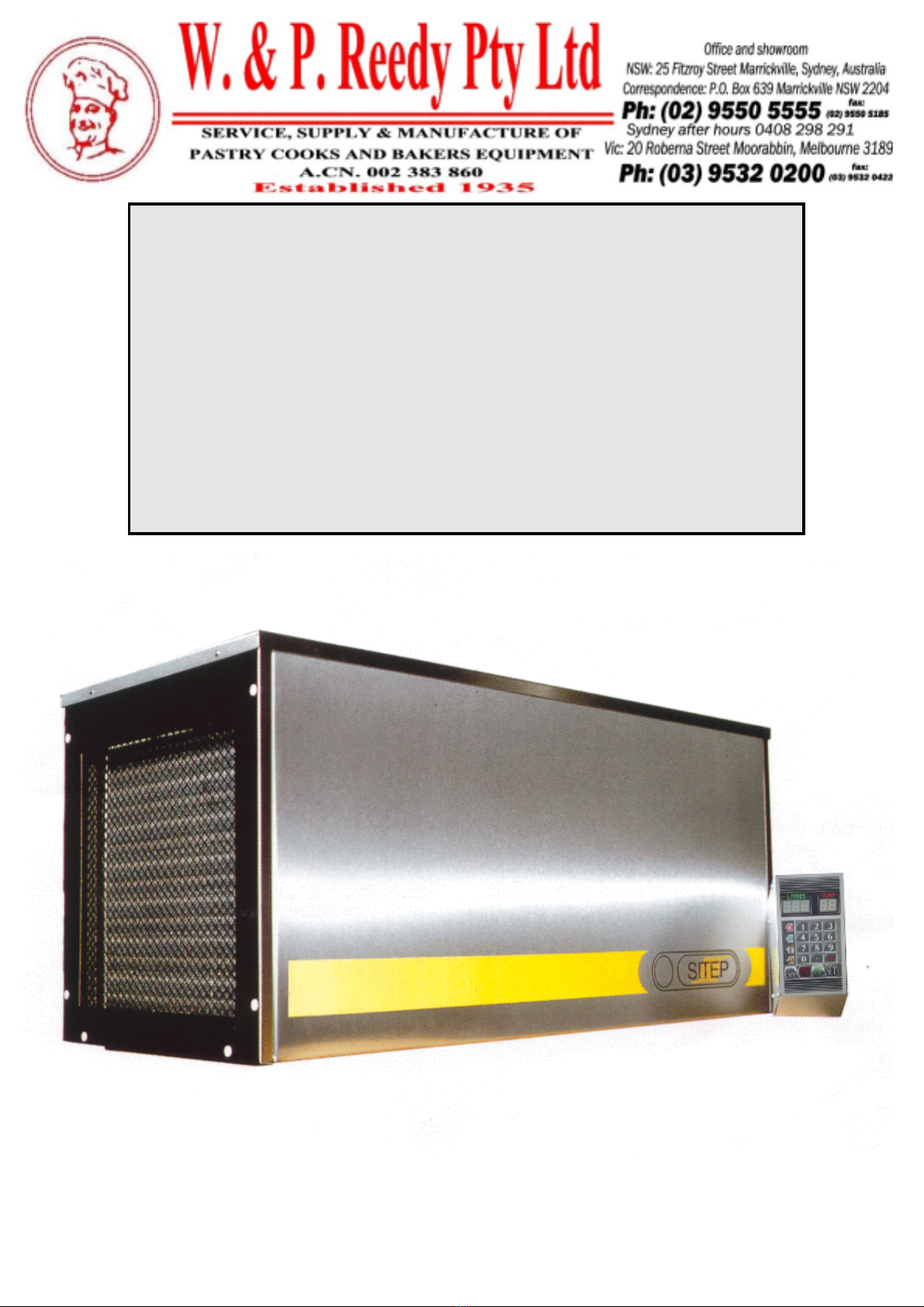
This machine should only be installed in a well ventilated area to ensure adequate
air circulation around the compressor. The environment where it is installed should
be free from dust and airborne particles, as this can block up the condenser. The
use of aerosol spray cans for greasing tins and trays will leave fine airborne grease
particles in the air, which when coming into contact with walls and equipment will
leave a very sticky substance which will attract dust. This is especially the case for
the condenser on the water cooler, if the water cooler is mounted above the spiral
mixer. Therefore we recommend that aerosols are not be used in the bakery for
greasing.
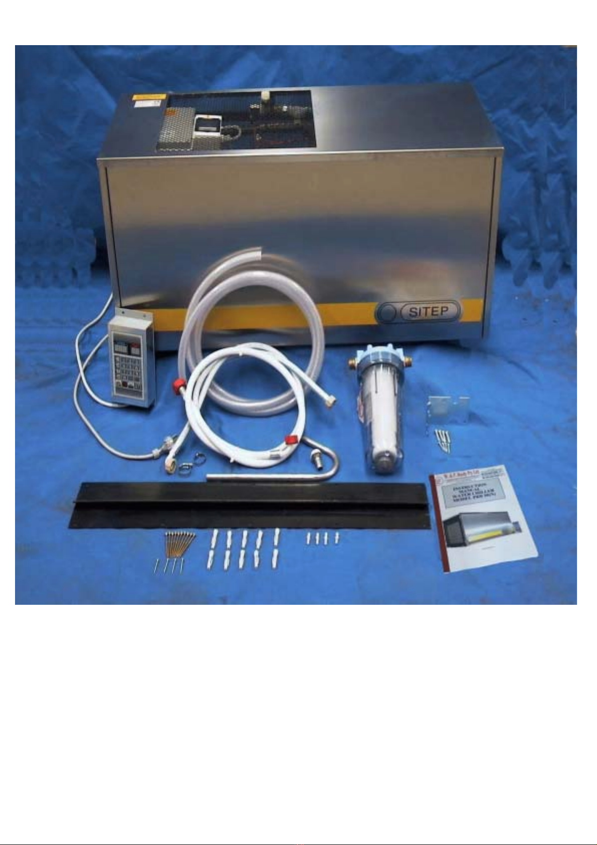
On delivery of the machine and after removing the packaging you should make sure
that all the components have been packed. A complete list of items is on page 2.
In case of any doubt you should consult the qualified personnel or the supplier.

Page 2
Components of package
1 x Water cooler unit complete with power cord and plug and control unit with cord
1 x Standard wall bracket
10 x Screws for wall bracket
10 x Wall plugs for wall bracket
2 x Hoses for inlet water with fittings attached (2 different styles)
1 x Hose for outlet water
1 x Water filter with 2 brass fittings
2 x Hose connectors
1 x Water filter housing bracket
1 x Stainless steel U fitting for outlet hose
1 x Fitting for the outlet on water cooler
2 x Hose clamps for outlet hose
3 x Screws for water filter bracket
3 x Wall plugs for water filter bracket
1 x Manual

Page 3
CHAPTER 1:
Useful information
NAME OF SUPPLIER W & P Reedy Pty Ltd.
ADDRESS 25 Fitzroy street Marrickville NSW
DAY TIME PHONE NO 02 9550 5555
AFTER HOURS PHONE NO 0408 298291
NAME OF MANUFACTURE Sitep
TYPE OF MACHINE Water Cooler (and heater for models
ending with “N”) and metre
Contacts in W & P Reedy P/L.:
MACHINE SALES: Lars Bryndum & Evan Huxtable
MACHINE USE: Lars Bryndum & Evan Huxtable
MAINTENANCE: Trent Sheridan
SPARE PARTS: Evan Huxtable
FINAL TEST RESULTS & CHECKS BEFORE SHIPPED:
Serial number of unit: ______________________________
Maximum deposit amount: ______________________________
Weight of 25.5 litres deposited: ______________________________
Checked by: ______________________________
Date: ______________________________

Page 4
CHAPTER 2:
Working Cycle
215 1 14
18
519
10
911
16 4
17 20
38
7
12
13

Page 5
A) Connect water to the Machine 1 through the supplied water filter.
Open the tap fully.
B) Connect electricity to machine 2 and turn on the power at the
power point.
C) Check that the earth leakage switch(this switch provides protection
to the operator and in case of variations in current)15 is turned
on.
D) To turn the machine on. Use the “ON/OFF” button 3 on the
control panel 4 Press for 3 seconds.
E) Water tank will fill with water 14.
F) When the water tank is full the water will stop automatically and
the recirculating pump starts.
G) The water temperature will automatically appear on the control
panel display 5 .
H) Set the controls to the required cooling or heating temperature in
the models ending with “N”. (Difference between cut in and out
temperature is 2 degrees.) To set the required temperature. Press
“SET” 7 , the temperature display 5 will flash press “CE” 8 to
clear previous setting, enter the temperature that you require by
using the numerical key pad 11 (minimum temperature 2 degrees
and maximum 32 degrees for the heater units), leave for 30 seconds
or press “SET” . and the figures will stop flashing. The water cooler
will now either cool or heat up the water.
I) The compressor will start if the water is warmer then the set
required temperature and the ice cycle symbol light 9 on the
control unit will come on. For the heater models if the water is
cooler than the set temperature the element will start heating the
water and the sun symbols 10 will come on.
J) When the required temperature is reached the compressor will stop
and the ice cycle symbol light will go off. For the heater models the
element will switch off and the sun symbol will go out.
K) To enter the required quantity (litres) 18 of water to be deposited
press “CE” to clear the previous setting and then enter the required
amount using the key pad. To enter decimal litres press “.” 20 and
then the decimal amount required.

Page 6
L) To deposit the preset litres through the deposit hose 19, press
“START” 13 and the unit will automatically deposit the set amount
(the accuracy will be within 2%). You can stop the deposit at any
time by pressing “STOP” 12. The litre amount 18 remaining to be
deposited will flash, to complete the deposit press “START”. If you
want to cancel the deposit press “STOP” again. The machine resets
to the previous deposited amount.
M) When the “START” button is pressed the deposit light 16 will
light up.
N) When the “START” button is pressed the compressor, element,
recirculation pump and water fill will stop and or switch off if they
were on when the start button was pressed. (If not enough time is
given to allow the tank to fill and the set temperature to be reached
you will not be able to get a full deposit at the right temperature.)
O) After the set quantity of water has been deposited the deposit pump
will stop and the tank will automatically commence filling.
P) At the end of the day when you have finished your production.
Press “ON/OFF” to turn the machine off. (It is not recommended
that you leave the machine on when not in use. Leaving the machine
on will cause excess wear and tear on working parts, therefore this
may reduce the life of the machine.)
Q) If the machine overheats during a working cycle the red warning
light 17 will come on.

Page 7
CHAPTER 3:
INSTALLATION AND LOCATION GUIDE:
The machine must be installed in an environment in which the temperature does not
exceed 30 degrees Celsius.
!
The machine should be fixed horizontally to a solid brick wall by the bracket
provided using all the ten plugs to spread the load of the unit evenly. Other
options are a stand which should be fixed to the wall, or a special wall bracket
which will enable fixing onto Bessa brick walls. After the bracket or stand has
been fastened to the wall, make sure that it is stable, as the machine weighs
140Kg when full. Position the electric control unit in a location where no
water is likely to splash on it and away from direct sunlight.
!
Position the machine in a location where there is adequate ventilation (airflow)
ie. not in a recess in the sealing and not in front of airconditioner inlet/outlet.
as the machine produces heat and requires air circulation to remain cool. i.e.
not in recesses where the air cannot circulate around the machine.
!
If the water cooler is to be placed in the ceiling, please ensure that there is easy
access for cleaning, maintenance removal if necessary and service. (Any cost
incurred in removing from, and reinstalling the water chiller in the ceiling
cavity is not covered by warranty.)
!
Ensure that the area where the machine is to be installed is a clean, dust free
and free of vermin.
Follow the diagram in the chapter 6 “ INSTALLATION AND FINAL TEST” for
correct positioning and location.
!
Connect the machine to a source of drinking water with a maximum pressure
of 3 bars. POLLUTED WATER SHOULD NOT BE USED IN ANY
INSTALLATION. DO NOT USE HOT WATER.
!
For Electrical connection see chapter 6.
!
The machine is designed to cool (or heat in models “N”) drinking water.
!
The machine should be used by an operator who must have read through this
manual.

Page 8
CHAPTER 4:
TECHNICAL DATA:
REFRIGERATED/HEATED
MODELS
PR50 PR50N PRR50 PRR50N
Capacity lt 50 50 50 50
Weight empty kg 70 70 90 90
Weight full kg 120 120 140 140
Voltage 240, 50 Hz single phase
Rapid cooling + 18 to + 3 in 15minuts
Normal cooling 1 hour
Built in heater
Heater power 240 volt watt 1500 1500
Compressor size hp 1/3 1/3 1.2 1.2
Ce manuel convient aux modèles suivants
3
Table des matières


