Simrad S5100 Manuel utilisateur

ENGLISH
S5100 Sonar module
Installation manual
simrad-yachting.com


Preface
Disclaimer
As Navico is continuously improving this product, we retain the right to make changes to the
product at any time which may not be reflected in this version of the manual. Please contact
your nearest distributor if you require any further assistance.
It is the owner’s sole responsibility to install and use the equipment in a manner that will not
cause accidents, personal injury or property damage. The user of this product is solely
responsible for observing maritime safety practices.
NAVICO HOLDING AS AND ITS SUBSIDIARIES, BRANCHES AND AFFILIATES DISCLAIM ALL
LIABILITY FOR ANY USE OF THIS PRODUCT IN A WAY THAT MAY CAUSE ACCIDENTS, DAMAGE
OR THAT MAY VIOLATE THE LAW.
This manual represents the product as at the time of printing. Navico Holding AS and its
subsidiaries, branches and affiliates reserve the right to make changes to specifications
without notice.
Governing Language
This statement, any instruction manuals, user guides and other information relating to the
product (Documentation) may be translated to, or has been translated from, another
language (Translation). In the event of any conflict between any Translation of the
Documentation, the English language version of the Documentation will be the official
version of the Documentation.
Copyright
Copyright © 2016 Navico Holding AS.
Warranty
The warranty card is supplied as a separate document.
In case of any queries, refer to the brand website of your display or system: www.simrad-
yachting.com.
Compliance statements
This equipment complies with:
•CE under EMC directive 2014/30/EU
•The requirements of level 2 devices of the Radio communications (Electromagnetic
Compatibility) standard 2008
The relevant Declaration of conformity is available in the product's section at the following
website: www.simrad-yachting.com.
About this manual
Intended audience
This manual is a reference guide for installing the S5100. The manual is written for marine
electronics technicians, and assumes some prior knowledge and skills relevant to the type of
work to be carried out.
Important text conventions
Important text that requires special attention from the reader is emphasized as follows:
ÚNote: Used to draw the reader’s attention to a comment or some important information.
Warning: Used when it is necessary to warn personnel that they should
proceed carefully to prevent risk of injury and/or damage to equipment/
personnel.
Preface | S5100 Installation Manual 3

Trademarks
Navico®is a registered trademark of Navico.
Simrad®is used by license from Kongsberg.
NMEA®and NMEA 2000®are registered trademarks of the National Marine Electronics
Association.
4Preface | S5100 Installation Manual

Contents
6 Introduction
6 Overview
6 Parts included
7 Connectors and LED location
8 Installation
8 Mounting location
8 Transducer installation
9 Wiring
9 Guidelines
9 Grounding the unit
10 Power connection
11 Connecting the S5100 to MFD systems
12 Transducer connection
14 Troubleshooting
14 LED indicators
15 Maintenance
15 Preventive maintenance
15 Checking the connectors
15 Software update
16 Spare parts and accessories
16 S5100 Spare parts and accessories
16 Transducers
17 Technical specifications
17 S5100
18 Dimensional drawings
18 S5100
Contents | S5100 Installation Manual 5

Introduction
Overview
The S5100 is a networked triple CHIRP module including 3 independent sonar channels. This
allows for simultaneous use of High, Medium and Low CHIRP, and for dual independent
ranges on a single screen. In addition, each frequency range can be viewed on connected
MFDs in the network.
The module is compatible with a variety of Navico's Multi-Function Displays (MFDs). See
more details on the S5100 website on www.simrad-yachting.com.
Parts included
ENGLISH
Installation Manual
bandg.com
ENGLISH
Installation Manual
bandg.com
1
2
8
34
5
6
7
1S5100 unit
2(4x) Fixing screws, Phillips stainless steel, 25 mm (1")
3Power cable, 2 m (6.5 ft)
4Ethernet cable, 1.8 m (6 ft)
5(3x) 7 to 9 pin adapter cables, 0.6 m (2 ft)
6Fuse holder
7Fuse, 5 Amp
8Documentation pack
1
6Introduction | S5100 Installation Manual
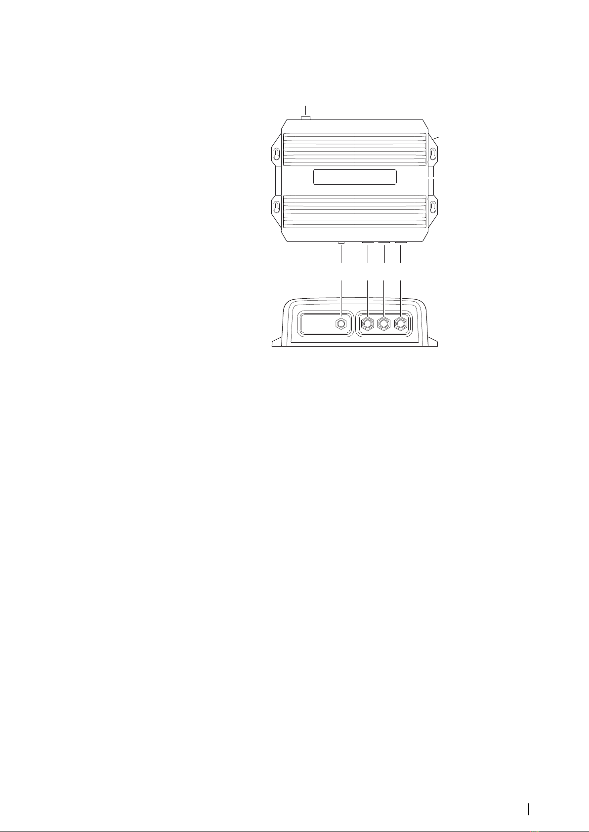
Connectors and LED location
1
2
3
65 7
4
1Power connector
2Grounding screw
3LED status indicators
4Ethernet connector
5Sonar channel 1
6Sonar channel 2
7Sonar channel 3
Introduction | S5100 Installation Manual 7

Installation
Mounting location
Choose the mounting locations carefully before you drill or cut.
For overall width and height requirements, refer to "Dimensionaldrawings" on page 18.
Do not mount any part where it can be used as a hand hold, where it might be submerged,
or where it will interfere with the operation, launching, or retrieving of the boat.
The unit should be mounted so that the operator can easily see the LED status indicators.
Check that it is possible to route cables to the intended mounting location.
Leave sufficient clearance to connect all relevant cables.
The unit can be mounted on a horizontal or on a vertical surface. Create drip loops when the
unit is mounted on a vertical surface with connections exiting upwards.
Before cutting a hole in a panel, make sure that there are no hidden electrical wires or other
parts behind the panel.
Ensure that any holes cut are in a safe position and will not weaken the boat’s structure. If in
doubt, consult a qualified boat builder, or marine electronics installer.
ÚNote: Where flush mounted, the enclosure should be dry and well ventilated. In small
enclosures, it may be required to fit forced cooling.
Warning: Inadequate ventilation and subsequent overheating of the unit
may cause unreliable operation and reduced service life. Exposing the unit
to conditions that exceeds the specifications could invalidate your warranty.
– refer to "Technical specifications" on page 17.
Transducer installation
For transducer installation information, refer to separate installation instructions included
with the transducer.
2
8Installation | S5100 Installation Manual

Wiring
Guidelines
Don't:
•make sharp bends in the cables
•run cables in a way that allows water to flow down into the connectors
•run the data cables adjacent to radar, transmitter, or large/high current carrying cables or
high frequency signal cables.
•run cables so they interfere with mechanical systems
Do this:
•make drip and service loops
•use cable-tie on all cables to keep them secure
•solder/crimp and insulate all wiring connections if extending or shortening the cables.
Extending cables should be done with suitable crimp connectors or solder and heat
shrink. Keep joins as high as possible to minimize possibility of water immersion.
•leave room adjacent to connectors to ease plugging and unplugging of cables
Warning: Before starting the installation, be sure to turn electrical power
off. If power is left on or turned on during the installation, fire, electrical
shock, or other serious injury may occur. Be sure that the voltage of the
power supply is compatible with the unit.
Warning: The positive supply wire (red) should always be connected to
(+) DC with the supplied fuse or a circuit breaker (closest available to fuse
rating).
Grounding the unit
For additional safety, install grounding cable in ground screw hole as indicated on the
illustration. Recommended 16 awg wire.
3
Wiring | S5100 Installation Manual 9

Power connection
The unit is designed to be powered by a 12 or 24 V DC system. It is protected against reverse
polarity, under voltage and over voltage (for a limited duration).
3
4
1
2
Unitsocket (male)
1
2
3
4
Cableplug(female)
Key Purpose Color
1DC negative Black
2Not used Blue
3Power control Yellow
4+12/24 V DC Red
Power control
The unit has no power key and will turn on when power is applied.
If the unit is connected directly to the vessel’s battery, the module will continue to draw
power even when it is not in operation. It is recommended that the yellow power cable wire
be fitted with an optional on/off switch, allowing the unit to be powered off when not in use.
12 - 24 V DC
+_
4
1
3
2
(n/c)
Some MFD systems can be configured for power control. When the S5100 is used in such
systems it is recommended to connect the unit to the power control bus and set the MFD to
power control master. Refer to your MFD documentation for more information.
12 - 24 V DC
2
1
34
4 1
3
+_
2
(n/c)
5
Key Purpose Color
1DC negative Black
2Not connected Blue
3Power control Yellow
4+12/24 V DC Red
5Power control bus
10 Wiring | S5100 Installation Manual
Table des matières
Manuels Unité de contrôle populaires d'autres marques

Festo
Festo Compact Performance CP-FB6-E Manuel de la liste des pièces

Elo TouchSystems
Elo TouchSystems DMS-SA19P-EXTME Manuel utilisateur

JS Automation
JS Automation MPC3034A Manuel utilisateur

JAUDT
JAUDT SW GII 6406 Series Guide rapide

Spektrum
Spektrum Air Module System Manuel utilisateur

BOC Edwards
BOC Edwards Q Series Manuel utilisateur


