SIMCom Wireless Solutions SIM5320AL EVB Manuel utilisateur
Development Kit Manual
SIM5320AL_EVB_User Guide_V1.01

Document Title: SIM5320AL EVB User Guide
Version: 1.01
Date: 2014-08-20
Status: Release
Document Control ID: SIM5320AL_EVB_User Guide_V1.01
General Notes
SIMCom offers this information as a service to its customers, to support application and
engineering efforts that use the products designed by SIMCom. The information provided is
based upon requirements specifically provided to SIMCom by the customers. SIMCom has
not undertaken any independent search for additional relevant information, including any
information that may be in the customer’s possession. Furthermore, system validation of this
product designed by SIMCom within a larger electronic system remains the responsibility of
the customer or the customer’s system integrator. All specifications supplied herein are
subject to change.
Copyright
This document contains proprietary technical information which is the property of SIMCo
Limited., copying of this document and giving it to others and the using or communication of
the contents thereof, are forbidden without express authority. Offenders are liable to the
payment of damages. All rights reserved in the event of grant of a patent or the registration of
a utility model or design. All specification supplied herein are subject to change without
notice at any time.
Copyright © Shanghai SIMCom Wireless Solutions Ltd. 2011

Smart Machine Smart Decision
SIM5320AL EVB User Guide 20.08.2014
2
Contents
Contents...............................................................................................................................................2
Figure Index........................................................................................................................................ 2
Table Index........................................................................................................................................3
Version History................................................................................................................................... 3
1 Overview.......................................................................................................................................... 4
2 SIM5320AL EVB............................................................................................................................ 5
3 EVB accessories...............................................................................................................................7
4 Accessory Interface.......................................................................................................................... 8
4.1 Power Interface.......................................................................................................................8
4.2 SIM card interface..................................................................................................................9
4.3 Antenna Interface................................................................................................................. 10
4.4 RS232 Interface....................................................................................................................10
4.5 Operating Status LED.......................................................................................................... 11
4.6 USB interface....................................................................................................................... 12
4.7 Switch interface....................................................................................................................13
4.8 IO interface...........................................................................................................................14
5 Quickly start................................................................................................................................... 16
5.1 Running................................................................................................................................ 16
5.2 Installing Driver................................................................................................................... 16
5.3 Connecting Net and calling..................................................................................................17
5.4 Downloading........................................................................................................................ 17
5.5 Turning off............................................................................................................................18
6.6 Measuring the current consumption.....................................................................................18
Figure Index
FIGURE 1: EVB VIEW............................................................................................................................ 6
FIGURE 2: EVB ACCESSORY............................................................................................................... 7
FIGURE 3: POWER SELECTION JUMPER...........................................................................................8
FIGURE 5: SIM CARD SOCKET............................................................................................................ 9
FIGURE 6: MAIN ANTENNA CONNECTOR...................................................................................... 10
FIGURE 8: SERIAL PORT.....................................................................................................................10
FIGURE 9: STATUS LED.......................................................................................................................11
FIGURE 10: USB INTERFACE............................................................................................................. 12
FIGURE 11: SWITCH INTERFACE...................................................................................................... 13
FIGURE 12: IO INTERFACE.................................................................................................................14
FIGURE 14: USB INTERFACE UPDATE PROCEDURE....................................................................18
FIGURE 15: CURRENT CONSUMPTION IN THE SLEEP MODE.................................................... 19
Smart Machine Smart Decision
SIM5320AL EVB User Guide 20.08.2014
3
Table Index
TABLE 1:SIM5320 EVB KEY FEATURES.............................................................................................4
TABLE 2: POWER SUPPLY.................................................................................................................... 8
TABLE 4: SIM CARD SOCKET..............................................................................................................9
TABLE 5: SERIAL INTERFACE........................................................................................................... 10
TABLE 6: NETWORK STATUS LED.................................................................................................... 11
TABLE 7: USB INTERFACE................................................................................................................. 12
TABLE 8: SWITCH INTERFACE.......................................................................................................... 13
TABLE 9: IO INTERFACE.....................................................................................................................14
Version History
Data Version Description of change Author
2014-08-20 1.01 Origin 3G Team
Smart Machine Smart Decision
SIM5320AL EVB User Guide 20.08.2014
4
1 Overview
This document gives the usage of SIM5320AL EVB, user can get useful information about the
SIM5320AL EVB quickly through this document. All the functions of the SIM5320AL can be
used by this board.
NOTE: This document is subject to change without notice at any time.
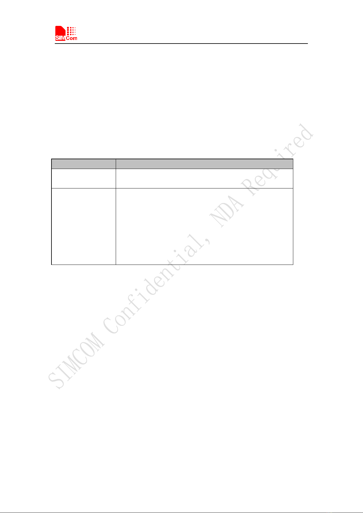
Table 1:SIM5320AL EVB Key features
Feature Implementation
Power supply 1: DC 6.0V~9.0V
2: USB 5.0V power supply
functions UART interface
USB2.0 interface
SIMCARD interface
I2C interface
ADC interface
POWER_ON key/Reset key
RF enable/disable (flight mode) switch
UART Control switch
Smart Machine Smart Decision
SIM5320AL EVB User Guide 20.08.2014
5
2 SIM5320AL EVB

Smart Machine Smart Decision
SIM5320AL EVB User Guide 20.08.2014
6
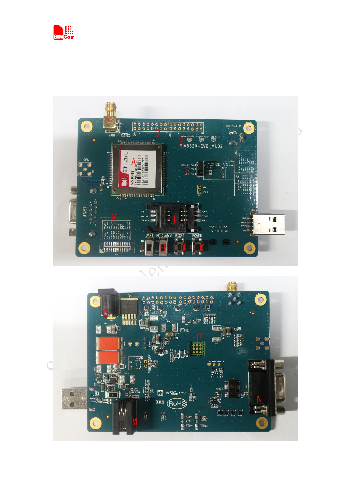
Figure 1: EVB view
A: SIM5320AL module
B: Reset keypad
C: Power on/off keypad
D: IO interface 1(including GPIO, ADC, SPI, etc)
E: LED indicator(including network status,operating status)
F: Power supply selection jumper
G: UART enable/disable switch
H: RF enable/disable (flight mode) switch
I: USB connector
J: SIM card socket
K: IO interface 2(including PCM,GPIO, UART, I2C, etc)
L: Main antenna SMA
M: Handset connector
N: UART connector
O: Adapter connector
P: SIM5320AL JTAG test point
All hardware Sub-interfaces included in SIM5320AL EVB are described in detail in following
chapters.
Smart Machine Smart Decision
SIM5320AL EVB User Guide 20.08.2014
7
3 EVB accessories
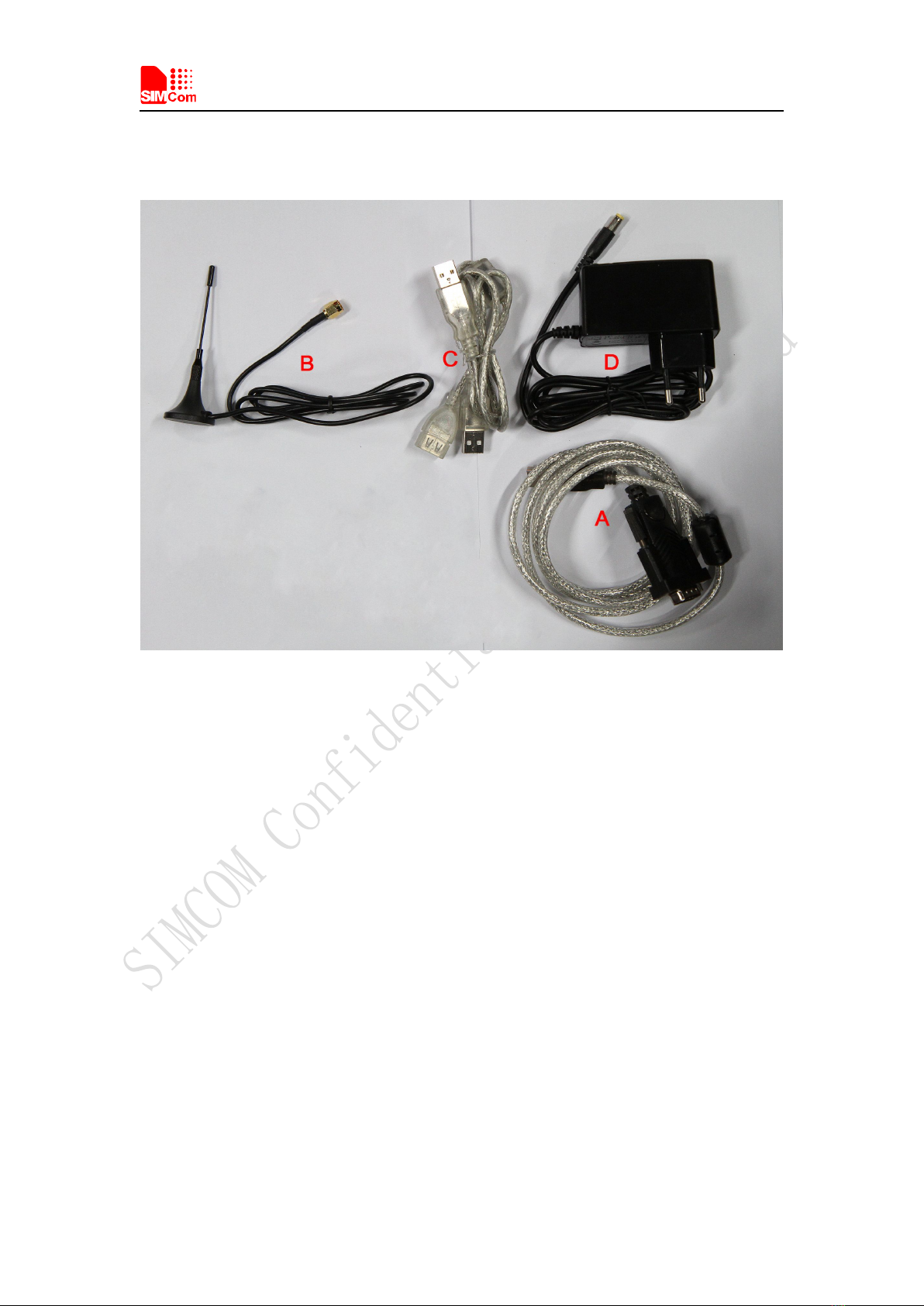
Figure 2: EVB accessory
A: USB to UART cable
B: RF antenna
Antenna Model: WT-C&G-28-90
Frequency Range (MHz) 824 ~ 960 1710 ~ 1990
VSWR ≤1.5 (900MHz) ≤2 (1800MHz)
Gain: 1dBi
Input Impedance (Ω): 50
Polarization Type: Vertical
Connector Type: SMA
C: USB cable
D: 6V DC adapter
NOTE: The maximum gain of the RF antenna gain should not exceed 1dBi for end-users.
Smart Machine Smart Decision
SIM5320AL EVB User Guide 20.08.2014
8
4 Accessory Interface
4.1 Power Interface
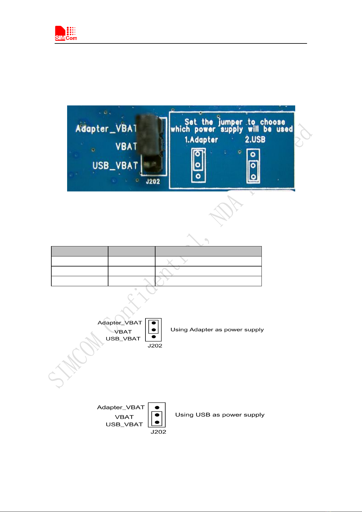
Figure 3: Power selection jumper
Table 2: Power supply
Signal Input/Output Description
Adapter_VBAT O 3.8V/2A DC source input
USB_VBAT O 3.8V/0.5A DC source input
VBAT I DC source input
If user wants to use DC adapter as power supply, Adapter_VBAT should be connected to VBAT
on J202 through a jumper as following figure shows.
This board could be powered by USB bus. User should connect the USB pin. USB_VBAT is the
USB power out.If user wants to use USB VBUS to power up the module, please connect
connector VBAT with connector USB_VBAT as following figure shows.and disconnect
Adapter_VBAT.
Smart Machine Smart Decision
SIM5320AL EVB User Guide 20.08.2014
9
4.2 SIM card interface
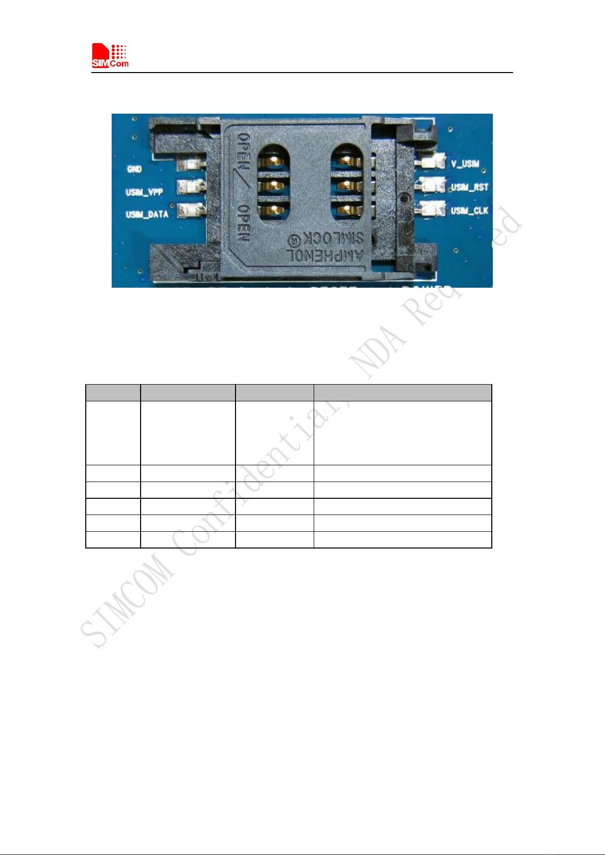
Figure 4: SIM card socket
Table 3: SIM card socket
Pin Signal Input/Output Description
1V_USIM O
USIM Card Power output automatic
output on USIM mode,one is
3.0V±10%, another is 1.8V±10%.
Current is about 10mA.
2 USIM_RESET O USIM Card Reset
3 USIM_CLK O USIM Card Clock
4 GND Ground
5 SIM_VPP O
V_USIM
6 USIM_DATA I/O
USIM Card data I/O
Table des matières
Autres manuels SIMCom Wireless Solutions Carte mère

Manuels Carte mère populaires d'autres marques


Telit Wireless Solutions
Telit Wireless Solutions SL869-3DR Manuel utilisateur

Gigabyte
Gigabyte GA-9IVDT Manuel utilisateur

Texas Instruments
Texas Instruments ADS8372EVM Manuel utilisateur

Commell
Commell MS-C73 Manuel utilisateur

IBT Technologies
IBT Technologies MB860 Manuel utilisateur

Nvidia
Nvidia TEGRA DG-04927-001_V01 Manuel utilisateur


